
XL-7 2WD V6-3.6L (2007)
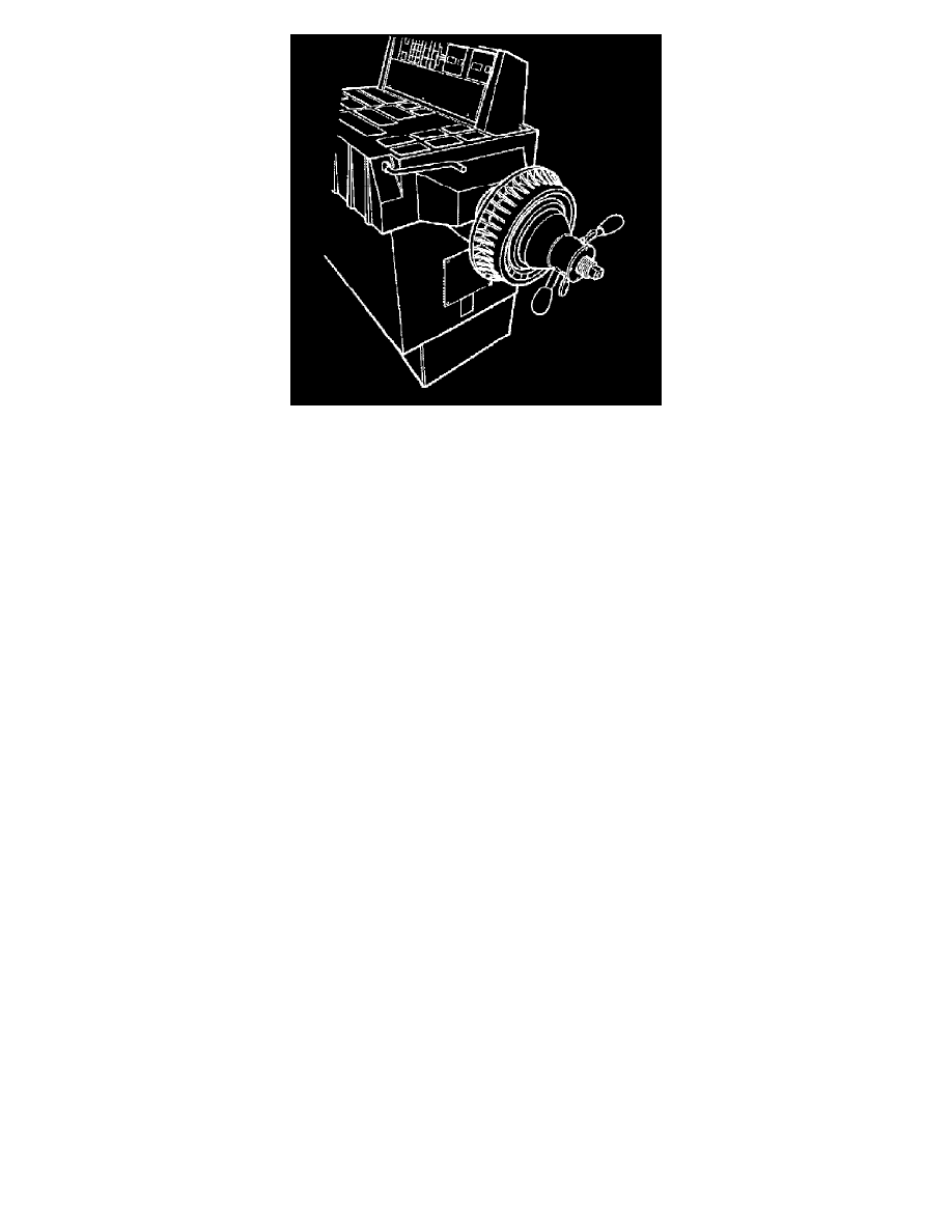
7. If a brake rotor was replaced as a result of following the previous steps, or if necessary to confirm the results obtained during the previous steps,
and/or to check the non-drive axle components, perform the following:
a. Mount the brake rotor/drum on a balancer in the same manner as a tire and wheel assembly.
NOTE: Check brake rotors/drums for static imbalance only; ignore the dynamic imbalance readings.
b. Inspect the rotor/drum for static imbalance.
There is not a set tolerance for brake rotor/drum static imbalance. However, any brake rotor/drum measured in this same manner which is over
21 g (3/4 oz) may have the potential to cause or contribute to a vibration. Rotors/drums suspected of causing or contributing to a vibration
should be replaced. Any rotor/drum that is replaced should be checked for imbalance in the same manner.
Brake Rotor Assembled Lateral Runout Correction
Brake Rotor Assembled Lateral Runout Correction
NOTE:
^
Brake rotor thickness variation MUST be checked BEFORE checking for assembled lateral runout (LRO). Thickness variation exceeding the
maximum acceptable level can cause brake pulsation.
^
Brake rotor assembled lateral runout (LRO) exceeding the maximum allowable specification can cause thickness variation to develop in the brake
rotor over time, usually between 4,800-11,300 km (3,000-7,000 mi).
Review the following acceptable methods for bringing the brake rotor assembled LRO to within specifications. Determine which method to use for the
specific vehicle being repaired.
^
The indexing method of correcting assembled LRO is most effective when the LRO specification is only exceeded by a relatively small amount:
0.025 - 0.127 mm (0.001 - 0.005 in). Indexing is used to achieve the best possible match of high spots to low spots between related components.
^
The correction plate method of correcting assembled LRO involves the addition of a tapered plate between the brake rotor and the hub/axle flange.
The correction plate method can be used to correct LRO that exceeds the specification by up to 0.23 mm (0.009 in).
^
The on-vehicle brake lathe method is used to bring the LRO to within specifications through compensating for LRO while refinishing the brake
rotor.
If the assembled LRO cannot be corrected using these methods, then other components must be suspected as causing and/or contributing to the LRO
concern.
Brake Rotor Assembled Lateral Runout Correction - Indexing
Special Tool
^
J 39544-KIT Torque-Limiting Socket Set, or equivalent
^
J 45101-100 Conical Brake Rotor Washers
WARNING: Refer to [Brake Dust Caution].
NOTE:
^
Brake rotor thickness variation MUST be checked BEFORE checking for assembled lateral runout (LRO). Thickness variation exceeding the
maximum acceptable level can cause brake pulsation.
^
Brake rotor assembled LRO exceeding the maximum allowable specification can cause thickness variation to develop in the brake rotor over time,
usually between 4,800-11,300 km (3,000-7,000 mi).