
XL-7 4WD V6-2.7L (2003)
Power Door Lock Switch: Testing and Inspection
Operation Check
Power Door Lock Switch Circuit
Power Door Lock Switch Circuit
1. Disconnect negative (-) cable at battery.
2. Disconnect coupler of power door lock and keyless entry controller.
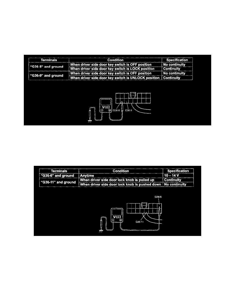
3. Check for continuity between the following terminals at each condition. If check result is satisfactory, this circuit is OK.
Door lock key and power door lock switch circuit (for keyless entry controller) specification
Door Knob Switch and Hazard Warning Lights Circuit
Door Knob Switch and Hazard Warning Lights Circuit
1. Disconnect negative (-) cable at battery.
2. Disconnect coupler of power door lock and keyless entry controller, and connect negative (-) cable at battery.
3. Check that the voltage and resistance between the following terminals are specifications. If check result is satisfactory, this circuit is OK.
Door knob switch and turn signal relay circuit(for keyless entry controller) specification