
XL-7 4WD V6-2.7L (2003)
Selector Shaft: Service and Repair
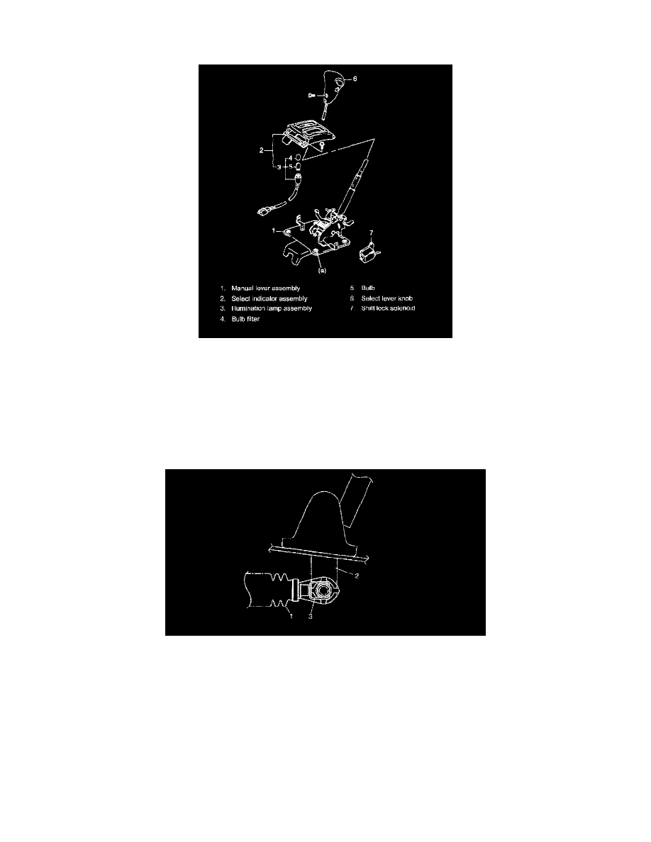
Manual Selector Assembly Components
Tightening torque
Manual selector assembly bolt (a): 18 Nm (1.8 kgf-m, 13.0 ft. lbs.)
Manual Selector Assembly Removal and Installation
Removal
1. Disconnect negative (-) cable at battery.
2. Remove console box.
3. Disconnect connector for illumination lamp, shift lock solenoid (if equipped)and overdrive OFF switch.
4. Remove selector assembly mounting bolts.
5. Disconnect selector cable (1) from manual selector assembly (2) expanding selector cable clip (3).
Installation
Reverse removal procedure to install manual selector assembly noting the following instructions.
^
Make sure that selector cable clip (3) hold selector cable (1) on manual selector assembly (2) securely.
^
Connect interlock cable end to cam.
^
Tighten manual selector assembly mounting bolts as specified torque.
Tightening torque
Manual selector assembly mounting bolts: 18 Nm (1.8 kgf-m, 13.5 ft. lbs.)
^
Upon completion of installation, confirm that brake (key) interlock system operates properly.
Manual Selector Assembly Inspection