Replacement of parts of the outer skin / doors, tailgates and luggage compartment lids, bonnets with folded edges
Replacement of parts of the outer skin / doors,
tailgates and luggage compartment lids, bonnets with folded
edges
Remove
Mode of Procedure for Removal
As a matter of principle, it is necessary to remove the
component, on which the outer skin is to be replaced, from the
vehicle and to remove any attaching parts present (on rear end
doors this includes windows attached with adhesive).
Outer skins are normally partially replaced (upper or lower
half) A dividing point is provided for this in the area of the
window line.
Adhesive bonds between the outer skin and the inner frame are
cut with flat scrapers or glass removal tools.
Spot welds are drilled out in the conventional way
Two possibilities are available for the removal of
outer skins with folded edges:
Method
Tool
Area of application
Chiselling off
Folded edge toolkit MKM-6392
on straight or slightly curved folded joints
Grinding through
Grinding disc
on straight and angled folded joints
Mode of Procedure with Folded Edge Toolkit
MKM-6392
Two chisels are included in the folded edge toolkit for use from
both sides
Important: The
chisels MKM-6392-1 and MKM-6392-2 should only be used manually as a matter
of principle and not in a compressed air chisel.
It is necessary to remove the seam sealant to reach the raised
seam more effectively.
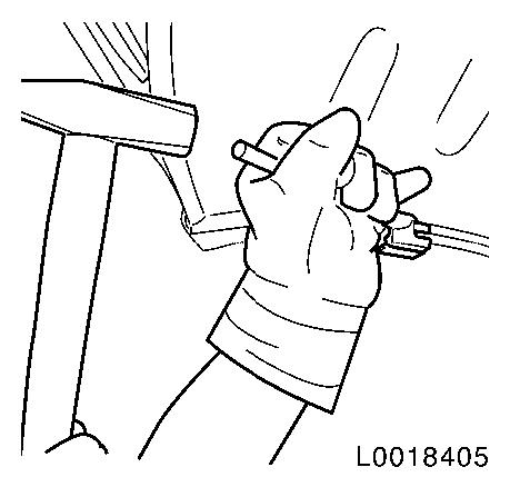
The blade of the MKM-6392-1 (or MKM-6392-2 ) is pressed under the flanged
folded joint with a suitable hammer. The outer plastic jaw serves
as a guide and should be run along the outside on the edge of the
component.
The blade opens the folded edge joint if the user hammers evenly
on the handle of the chisel.
The opened edge can then be opened up completely with a pair of
pliers and the outer skin removed from the frame.
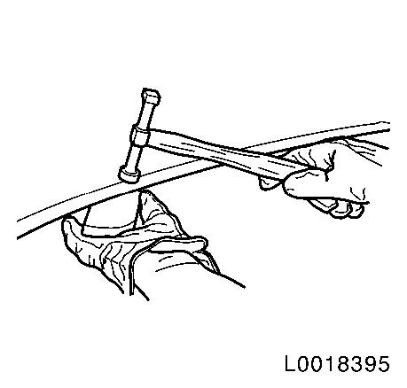
Mode of Procedure with Grinding Disc
Use an angle grinder with a grinding or toothed grinding
disc.
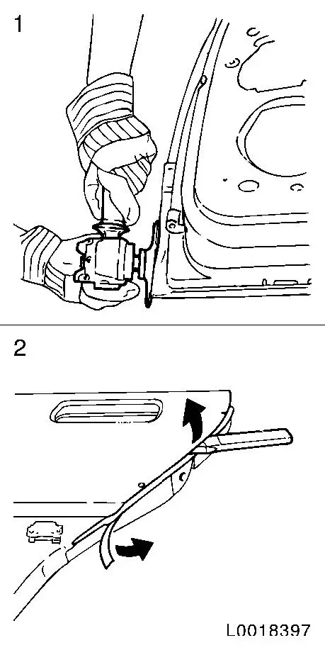
Cut through edge of component slowly and carefully applying a
low level of pressure evenly (1)
Important: Do not
damage the sheet metal lying in the folded edge joint!
A sufficient cutting depth has been reached when individual
layers of sheet metal become visible on the cut open edge.
Cut the individual layers of sheet metal with a flat chisel and
remove from the framework (2).
Install
Mode of Procedure for Installation
Remove residual sealant from panel frame. Grind welding flanges
on panel frame and new part down to bright metal. Cut down beads of
adhesive from inner framework to outer skin. Straighten panel frame
if necessary. Grind residues of spot welds smooth. If necessary,
work in dividing point between new part and outer skin.
Applying 1-Component Glass Adhesive
Clean surfaces of new component to be bonded using the cleaning
material from the kit, apply primer and allow to air dry.
Apply 1-component glass adhesive to cut down beads of
adhesive
Clean the flanges to be bonded on the new component and the
frame with the cleaning material from the kit.
Note: Only use the
adhesive cartridge in a suitable cartridge gun!
Lay a test bead (approx. 20 cm long), until the adhesive is
evenly mixed through.
Apply a bead of adhesive around the circumference of folded edge
joint and welding flanges.
Note: Leave at least
40 mm free in adhesive zones within the connection area of any
MIG-brazed seams which may be present.
Aligning the New Outer Skin Component
Lay new part on frame and align. Fix, e.g. with locking pliers.
Fit component on vehicle and align outer skin. Then remove
component from vehicle again.
Important: To
prevent indentations, place an underlay between the locking pliers
and the new outer skin component!
Several possibilities exist for making the folded
edge joint on the new outer skin.
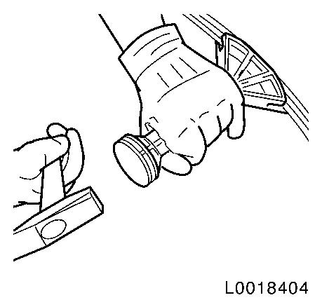
Pre- prepare joint with hammer-headed chisel
MKM-6392-4
Position hammer-headed chisel MKM-6392-4 and bend folded edge joint evenly around
the circumference within the working area provided by striking the
handle with a hammer.
Important: Do not
tilt hammer-headed chisel to avoid damage!
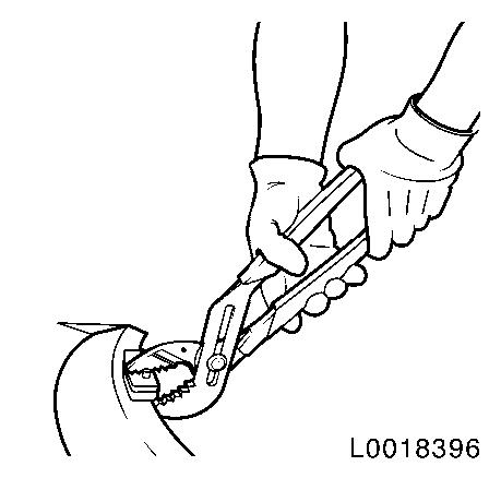
Close fold with folded joint pliers KM-6396
Position folded joint pliers KM-6396
with the inner working jaw on the outer skin. Close partially bent
folded edge joint by pressing closed with the folded joint pliers
completely and evenly around the edge.
Important: Do not
tilt folded joint pliers to avoid damage to the outer skin!
Course of fold with hammer and pad
Pre-fold folded flange with a suitable hammer whilst
simultaneously counterholding with a pad or block.
Complete folding of folded flange around the circumference with
hammer and block.
Resistance spot welding
Position spot welds as on old part.
Note: In the edge
area, the outer skin is only butt spot-welded from behind in some
places along the fold!
MIG-Brazing Butt Welds
MIG-braze joints when replacing tailgate outer skins and grind
down.
Aligning Folded Joint
Align and smooth flanged folded joint and outer skin with hammer
and block. If necessary, finish outer skin with body file to
produce a surface suitable for applying paint.
Sealing Folded Joint and Assembly
Paint on surface adhesive with a spatula or flat paintbrush as a
seam sealant and corrosion protection and allow to cure.
Prime folded joint
Note: Comply with
air-drying time for primer!
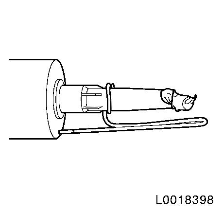
Apply body sealing compound around the circumference of the
folded edge. If necessary cut tip of cartridge to size and make a
spacer from wire to guide the cartridge tip along the edge of the
component and attach.
Note: Apply the seam
sealant as evenly as is undertaken in the works! Only brush in the
corner areas!
After completion of painting, fit attaching parts and apply
corrosion protection wax in the cavities.