|
Injectors, Remove and Install (X 12) Fuel
Distributor Pipe, Remove and Install (X 12 XE)
 Remove Remove
Remove air cleaner housing with hot film mass air flow meter and
air intake cover – see illustration "Air Ducts X 12 XE".
|
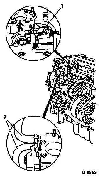
Detach accelerator Bowden cable (1) from curved disc and
bracket.
Detach coolant hoses (2) from throttle body.
Reduce fuel pressure with KM-J-34730-91 via testing port (arrow)
– collect escaping fuel in suitable container – observe
safety regulations and national legislation.
|
|
|
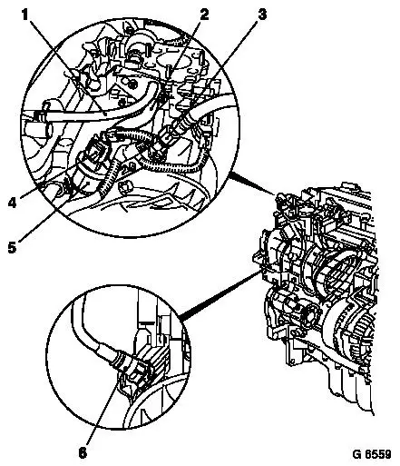
Detach fuel feed line (3) from fuel distributor pipe.
Detach engine vent hose (1) from cylinder head cover.
Disconnect wiring harness plug (4) from tank vent valve.
Remove vacuum hose for tank vent valve (2) from throttle
body.
Detach tank vent valve (5) from bracket and put to one side with
line.
Detach brake servo vacuum line (6) from intake manifold.
|
|
|
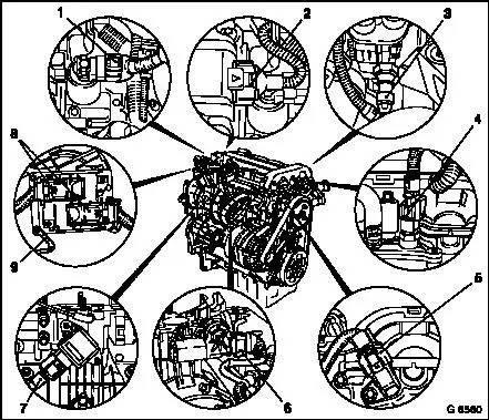
Disconnect or detach following wiring
harness plugs.
| 1. |
Exhaust gas recirculation valve |
| 2. |
Ignition module |
| 3. |
Oil pressure switch |
| 4. |
Coolant temperature sensor |
| 5. |
Camshaft sensor |
| 6. |
Throttle valve adjuster |
| 7. |
Throttle valve potentiometer |
| 8. |
Engine control unit |
| 9. |
Earth cable |
|
|
|
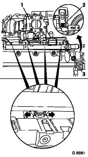
Detach throttle body (1) from intake manifold.
Remove fastening bolt (2) – put cable bunch bracket to one
side and remove engine transport shackle.
Disconnect injector plug strip (3) from intake manifold or fuel
distribution pipe (2 fastening bolts) and carefully remove from
injectors – spread fastening clips for this operation
(arrows).
Put plug strip with cable bunch to one side.
|
|
Remove fuel distributor pipe with injectors from intake
manifold.
|
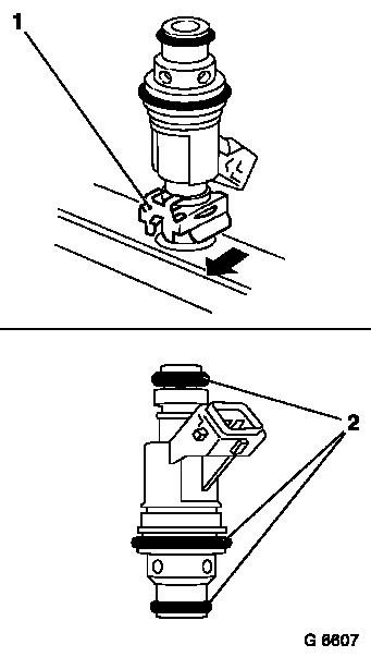
Detach retaining clamp (1) in direction of arrow and detach
injector from fuel distribution pipe – note installation
position.
 Install
Thinly coat new flanges (2) with clean engine oil and place upon
injection valves.
Install injectors in fuel distributor pipe and fasten with
retaining clamp – ensure installation position and seating
are correct.
Insert fuel distributor pipe in intake manifold together with
injectors.
|
|
Connect plug strip to injectors – plug strip must audibly
engage.
Attach injector plug strip to intake manifold with fuel
distribution pipe – tightening torque 8 Nm / 6 lbf. ft.
Attach engine transport shackle to cylinder head with cable
bunch bracket – tightening torque 20 Nm / 15 lbf. ft.
Attach throttle body with new gasket to intake manifold –
tightening torque 8 Nm / 6 lbf. ft.
Connect or attach all wiring connections which are connected to
the injectors plug strip.
Connect brake servo vacuum line to intake manifold.
Attach tank vent valve to bracket – tightening torque 6 Nm
/ 4 lbf. ft.
Attach vacuum hose for tank vent valve to throttle body.
Attach fuel feed lines to fuel distributor pipe –
tightening torque 15 Nm / 11 lbf. ft.
Attach engine vent hose to cylinder head cover.
Attach coolant hoses to throttle body.
Attach accelerator Bowden cable to curved disc and bracket.
Install air cleaner housing with hot film mass air flow meter
and air intake cover – see illustration "Air Ducts X 12
XE".
 Inspect
Charge cooling system – see operations "Cooling System,
Charge and Bleed" and "Cooling System, Check for Leaks".
Note: When removing
and installing or replacing the throttle body it is absolutely
essential that the adaptation values for the throttle valve in the
EE PROM of the engine control unit are deleted using TECH 2 –
see corresponding Checking Procedures.
|
