|
Transmission, Remove and Install
(F13/F13+/F17/F17+/F18)
Note: The following
parts must be converted when the transmission is replaced:
Only for transmission F17/F17+:
- Pressure line with fitting (vehicles up to MY 2002 only)
The drive unit must be aligned to the front axle body using KM-6173
and KM-6001-A in order to ensure correct alignment of the drive
unit after releasing the fastening bolts for the right and left
engine damping blocks. The attachment of KM-6173 and KM-6001-A is
described in the following.
 Remove Remove
|
If present: Remove lower engine compartment cover – see
operation "Lower Engine Compartment Cover, Remove and Install" in
group "A".
Remove front exhaust pipe, catalytic converter and centre
muffler.
 Install
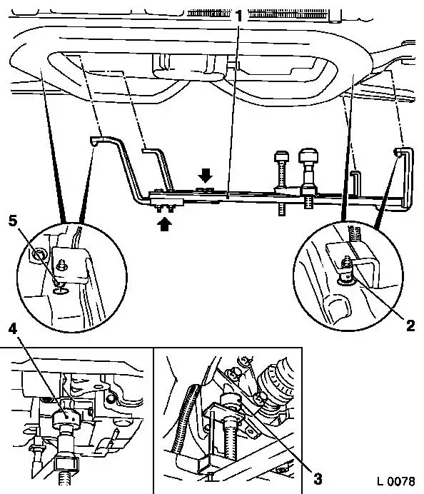
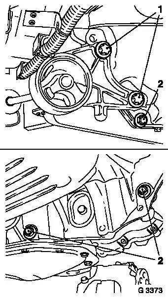
Attach KM-6173 (3) to front axle body – screw up support
bearing (2) until pins are seated flush in mount (1) on cylinder
block.
|
|
Install
|
|
Release fastening bolts (arrows) for adjustment rails on
KM-6001-A (1).
Insert KM-6001-A as illustrated – pins (2) and (5) must
engage in guide holes of front axle body. Tighten fastening bolts
for adjustment rails.
Screw up front support bearing (4) and rear support bearing (3)
up to contact at guide pins of front engine damping block and rear
engine damping block bracket – guide pins must sit free of
play in support bearings.
Remove
Remove front axle body – see operation "Front Axle Body,
Remove and Install" in group "E". The Tools KM-6173 and KM-6001-A
remain on the front axle body and must not be moved.
|
|
Remove air filter housing with air intake hose – see
illustration "Air Flow Guide" in group "J".
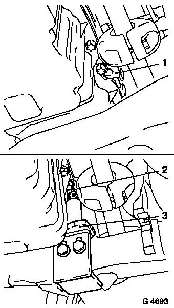
Remove fastening bolts (1) of right engine damping block from
right engine damping block bracket.
Detach wiring harness plug (5) from reversing lamps switch
(4).
Charge brake fluid reservoir to "MAX" and close off with dummy
plug.
Detach pressure line with connector (2) from central release
pressure line on clutch housing – at the same time release
and remove clamp (3) with screwdriver; then slightly bend clamp
together and re-insert in connector. Collect escaping fluid.
|
|
|
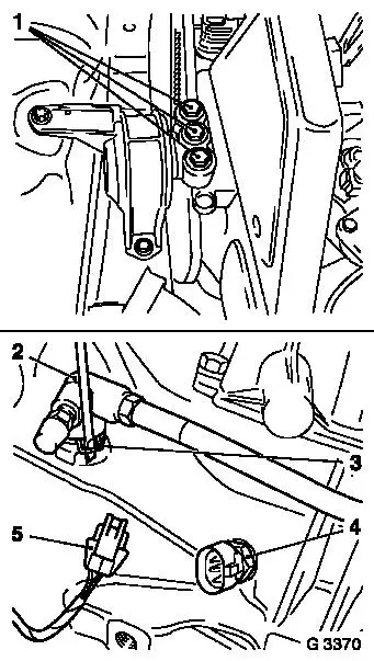
Remove left engine damping block fastening bolts (2) from left
engine damping block bracket.
Remove fastening bolts (1) for left engine damping block support
from transmission.
Remove engine damping block support.
Remove four upper fastening bolts (arrows) of transmission
– if necessary, pull coolant pipe upward and secure with
cable tie.
Lower engine with transmission approx. 5 cm on MKM-883-1 –
ensure that coolant hoses and wiring harnesses are not
stretched.
|
|
Remove axle shafts from transmission – see operation "Axle
Shaft, Remove and Install" in group "E". Axle shafts remain in
wheel hubs. Attach axle shafts to underbody.
Caution
Fluid escapes – place pan underneath and close off
apertures with plug.
Remove
|
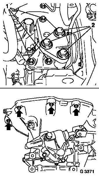
Remove front engine damping block fastening bolts (1) from
transmission. Remove front engine damping block.
Remove transmission housing fastening bolts (2) at fluid
sump.
|
|
Install
|
|
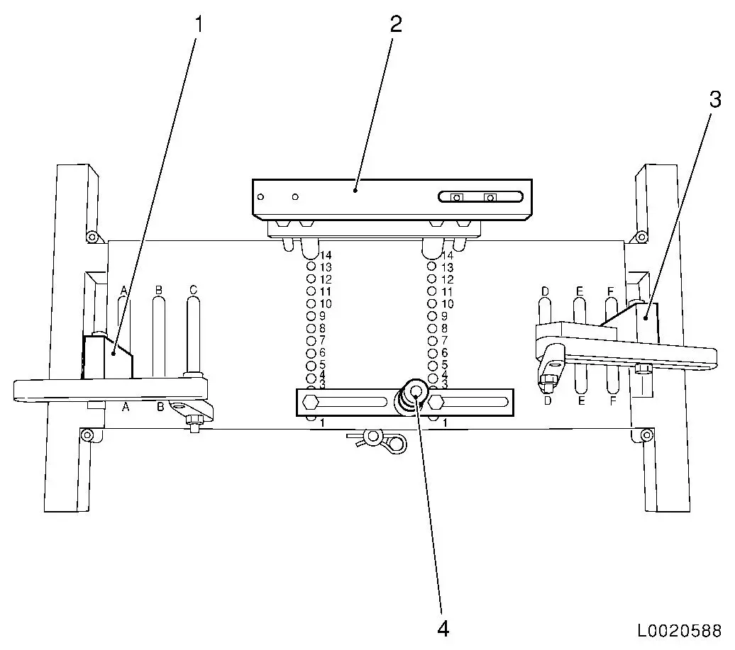
Set transmission mount DT-47648 on
KM-904 and preinstall as shown in illustration:
|
Part
|
Position on base plate
|
Name
|
|
DT-47648-2
(4)
|
2
|
Clutch housing support
|
|
DT-47648-3
(2)
|
14
|
Transmission housing support
|
|
DT-47648-5 left
(1)
|
A
|
Transmission support with swivel arm, rear
|
|
DT-47648-5 right
(3)
|
F
|
Transmission support with swivel arm, front
|
|
|
Caution
Manufacturer's instructions for transmission mount DT-47648 must
be observed.
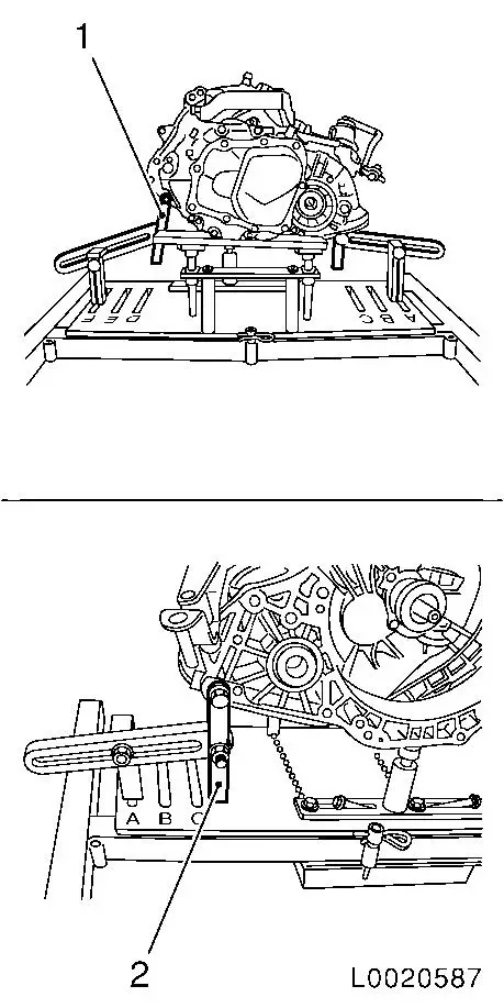
Attach transmission mount DT-47648 to transmission
Note: Loosen all bolt
connections on the swivel arms and supports down to the base plate
before positioning. Turn the supports as far down as possible using
the spindles.
Set transmission mount DT-47648 down with supports under
transmission
Tighten the bolt connections of the supports
Attach swivel arm (1) and (2) to transmission
Tighten the bolt connections in the swivel arm from the
transmission to the base plate
Note: Align the
swivel arms to minimize the leverage forces.
|
|
|
Remove
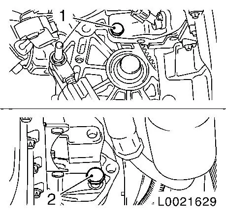
Remove front (2) and rear (1) transmission fastening bolts from
engine.
Press off transmission from engine block and carefully drain
– ensure that installation parts and wiring harnesses are not
damaged.
If necessary: Detach transmission from DT-47648.
Caution
Do not damage attaching parts when laying transmission down.
|
|
Remove
Attach transmission to DT-47648.
Caution
Follow manufacturer's instructions for DT-47648.
Install
Lift, align and attach transmission uniformly on engine.
Install lower front and rear transmission fastening bolts on
engine – tightening torque 60 Nm / 44 lbf. ft.
Remove
Detach DT-47648 from transmission.
Install
|
Install transmission on fluid sump – tightening torque 40
Nm / 29.5 lbf. ft.
Install front engine damping block on transmission –
tightening torque 60 Nm / 44 lbf. ft.
Detach axle shafts from underbody.
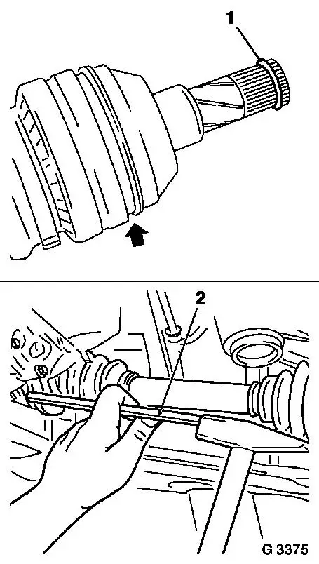
Install axle shaft in transmission: Attach new retaining ring
(1) to axle shaft.
Coat splines of axle shaft with transmission fluid.
Insert axle shafts into transmission and drive in against bead
of friction weld seam (arrow) with soft metal drift (2) or with
plastic hammer until retaining ring engages.
Move engine with transmission on MKM-883-1 into original
position.
|
|
Install front axle body – see operation "Front Axle Body,
Remove and Install" in group "E".
Caution
When installing the front axle body, ensure that support
bearings of KM-6001-A are correctly seated in the guide pins of the
front engine damping block and the rear engine damping block
bracket. Pins of KM-6173 must sit in the cylinder block mount. If
necessary: Correct installation location of engine and transmission
using MKM-883-1.
Do not yet install front exhaust pipe, catalytic converter,
centre muffler, battery and battery support.
Install
Install right engine damping block on engine damping block
bracket – tightening torque 55 Nm / 41 lbf. ft.
Install air intake hose and air filter housing – see
illustration "Air Flow Guide" in group "J".
Install left engine damping block main bracket on transmission
– tightening torque 35 Nm / 26 lbf. ft. Install left engine
damping block on left engine damping block main bracket, note
different bolt lengths – tightening torque 55 Nm / 41 lbf.
ft.
Install upper fastening bolts on transmission – tightening
torque 60 Nm / 44 lbf. ft.
Insert pressure line with connection piece into central release
pressure line on clutch housing – clamp engages audibly.
Connect wiring harness plug to reversing lamp switch.
Remove KM-6001-A and KM-6173.
Install front exhaust pipe, catalytic
converter and centre muffler with new gaskets and fastening
nuts.
|
|
Engine (thread)
|
Tightening torque
|
|
|
|
|
|
Front exhaust pipe to
|
X 16 SZR, Z 16 SE (M10)
|
35 Nm / 26 lbf. ft.
|
|
Exhaust manifold
|
X 12 XE, Z 12 XE (M10)
|
35 Nm / 26 lbf. ft.
|
|
|
X 14 XE, Z 14 XE, X 16 XEL, Z 16 XE, X 18 XE1, Z 18 XE, X 20
XEV, X 20 DTL (M8)
|
20 Nm / 15 lbf. ft.
|
|
|
X 17 DTL, Y 17 DT (M10x1.25)
|
20 Nm / 15 lbf. ft.
|
|
Centre muffler to
|
|
|
|
rear muffler
|
(M8x1)
|
12 Nm / 9 lbf. ft.
|
 Inspect
Check level of transmission fluid and correct if necessary
– see operation "Transmission Fluid Level, Check and Correct
(F13/F13+/F17/F17+/F18)".
Install
If present: Install lower engine compartment cover – see
operation "Lower Engine Compartment Cover, Remove and Install" in
group "A".
 Adjust Adjust
Adjust transmission shift linkage and tighten clamp bolt –
see operation "Transmission Shift Linkage, Adjust
(F13/F13+/F17/F17+/F18)".
Install
Install battery support – tightening torque 15 Nm / 11
lbf. ft. Install battery.
Inspect
Remove blind screw cap from brake fluid reservoir. Bleed
hydraulic clutch actuation – see operation "Hydraulic Clutch
Actuation, Bleed (F13/F13+/F17/F17+/F18/F23)". Top brake fluid
level up to "MAX" mark.
|
