|
Electro-Hydraulic Supply Unit, Remove and Install
or Replace (EHPS Gen. I)
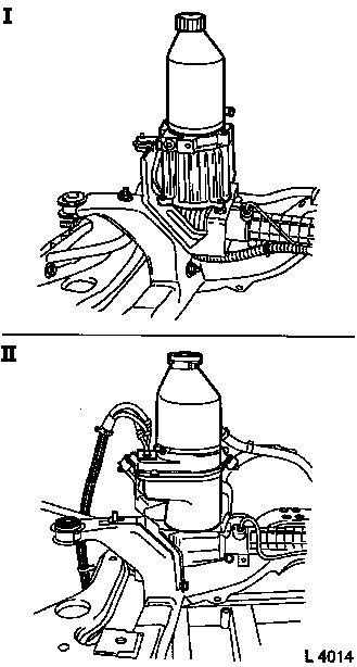
Note: Due to the use
of steering systems from different suppliers, two different
electro-hydraulic supply units are used. The main distinguishing
characteristic is the shape of the power steering fluid
reservoir:
|
Round Power Steering Fluid Reservoir = TRW
|
|
Angular Power Steering Fluid Reservoir = Delphi
|
The removal and installation procedure is described separately
below.
|
Electro-hydraulic Supply Unit, Remove and
Install(TRW):
Remove front axle body – see operation "Front Axle Body,
Remove and Install" in group "E".
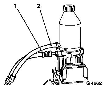
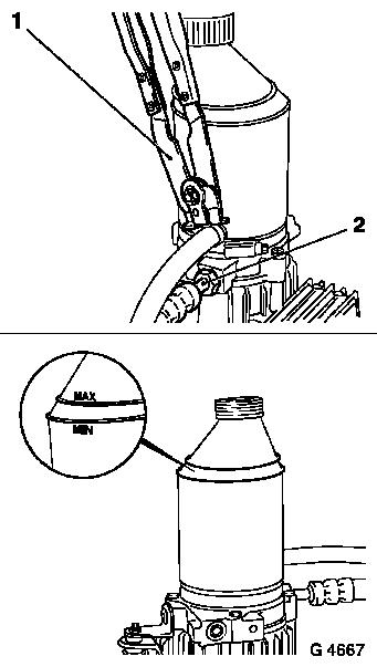
Detach pressure line (1) and return line (2) from
electro-hydraulic supply unit. Fluid will escape – place
collecting pan underneath.
Unclip steering wiring harness from front axle body and lay out
of the way – note cable routing.
|
|
 Remove Remove
|
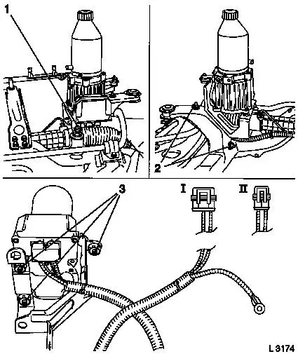
Detach fastening nuts (1) and (2) from steering gear and front
axle body. Remove electro-hydraulic supply unit with bracket and
steering wiring harness.
Remove fastening bolts (3) and remove electro-hydraulic supply
unit from bracket.
Caution
The electro-hydraulic supply unit can only be replaced together
with the steering wiring harness, disassembly is not anticipated.
The steering wiring harness as of MY 2000 is fitted with a 3-pin
(I) wiring harness plug (up to MY 2000: 2-pin design, II). When
replacing the electro-hydraulic supply unit, a corresponding
adapter can be obtained, if necessary, from "Aftersales".
|
|
 Inspect
|
Check damping bushings in bracket and replace if necessary.
 Install
Attach electro-hydraulic supply unit to bracket –
tightening torque 7 Nm / 5 lbf. ft.
Position electro-hydraulic supply unit with bracket on steering
gear and front axle body – note steering wiring harness.
Attach bracket for electro-hydraulic supply unit with fastening
nuts (2) on front axle body – tightening torque 22 Nm / 16
lbf. ft. Attach bracket for electro-hydraulic supply unit to
steering gear with fastening nut (1) – tightening torque 22
Nm / 16 lbf. ft.
Clip steering wiring harness onto front axle body – ensure
correct cable routing.
|
|
|
Attach pressure line (2) with new seal ring to electro-hydraulic
supply unit – tightening torque 30 Nm / 22 lbf. ft. Attach
return line with new retaining strap and KM-J-22610 (1) to
electro-hydraulic supply unit.
Unscrew fluid reservoir cover. Remove fluid screen from fluid
reservoir and check for impurities, clean carefully if necessary.
Insert fluid screen in fluid reservoir.
Fill fluid reservoir with special fluid to the "MAX" mark and
close cover.
Install front axle body – see operation "Front Axle Body,
Remove and Install" in group "E".
Charge and bleed hydraulic system – see operation
"Hydraulic System, Charge and Bleed (EHPS Gen. I)".
|
|
Electro-hydraulic Supply Unit, Remove and Install
(Delphi):
Remove
|
Remove front axle body – see operation "Front Axle Body,
Remove and Install" in group "E".
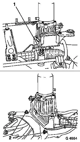
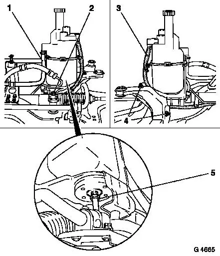
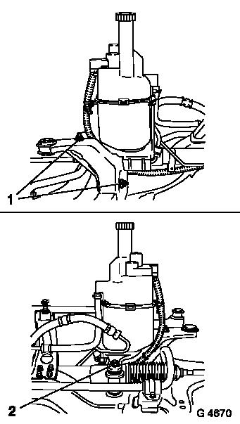
Detach pressure line (5) and return line (1) from
electro-hydraulic supply unit. Fluid will escape – place
collecting pan underneath. Unclip steering wiring harness (3) from
front axle body and lay bare – note cable routing.
Detach fastening nuts (2) and (4) from steering gear and front
axle body. Remove electro-hydraulic supply unit with bracket and
steering wiring harness from front axle body.
|
|
|
Caution
The electro-hydraulic supply unit can only be replaced together
with bracket and steering wiring harness, disassembly is not
anticipated.
Install
Position electro-hydraulic supply unit with bracket on steering
gear and front axle body – note steering wiring harness.
Attach bracket for electro-hydraulic supply unit to front axle
body with fastening nuts (1) – tightening torque 22 Nm / 16
lbf. ft. Attach bracket for electro-hydraulic supply unit with
fastening nut (2) to steering gear – tightening torque 22 Nm
/ 16 lbf. ft.
Clip steering wiring harness onto front axle body – ensure
correct cable routing.
|
|
|
Reattach pressure line with new seal ring to electro-hydraulic
supply unit – tightening torque 27.5 Nm / 20.5 lbf. ft.
Attach return line (4) to electro-hydraulic supply unit.
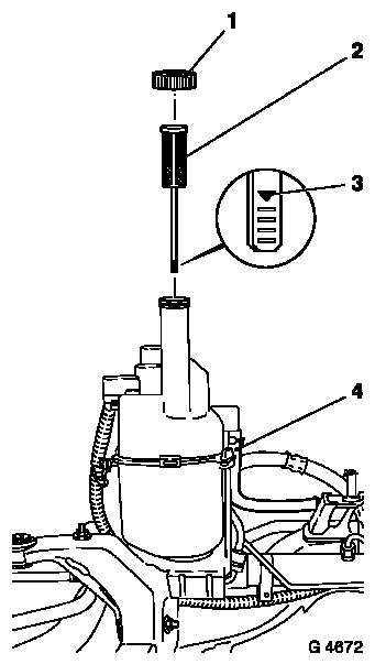
Unscrew cover (1) from fluid reservoir. Remove fluid screen with
fluid dipstick (2) from fluid reservoir and check for impurities,
cleaning carefully if necessary. Insert fluid screen with fluid
dipstick in fluid reservoir.
Fill fluid reservoir with special fluid until fluid reaches mark
(3). To prevent overfilling, remove fluid screen and dipstick and
check repeatedly. When finished, screw on closure cap.
|
|
Install front axle body – see operation "Front Axle Body,
Remove and Install" in group "E".
Charge and bleed hydraulic system – see operation
"Hydraulic System, Charge and Bleed (EHPS Gen. I)".
|