|
Cylinder Head, Remove and Install
Important: When
working on the fuel system it is essential to pay attention to
cleanliness as even the smallest dirt particles can lead to faults
in engine operation or in the fuel system. Open fuel connections
must be sealed with appropriate plugs from the Opel Parts Catalogue
(catalogue number: 45 06 154 / part number: 9201697). Sealing plugs
are only intended to be used once.
 Remove Remove
| 1. |
Remove exhaust manifold with turbocharger
| • |
with manual transmission
|
| • |
with automatic transmission 
|
|
| 3. |
Detach wiring harness
| • |
Disconnect 5x wiring harness plug
| – |
Pre-catalytic converter temperature sensor
|
|
| • |
Put wiring harness to side
|
|
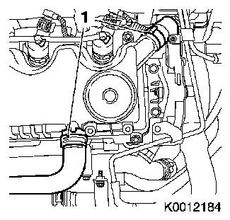
| 4. |
Detach 2x hose (1) from cylinder housing cover
|
|
|
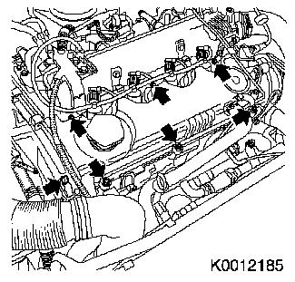
| 5. |
Remove cylinder head cover
| • |
Unscrew 7x bolt (arrows) in a spiral from the outside
inward
|
|
|
|
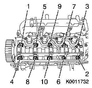
| 6. |
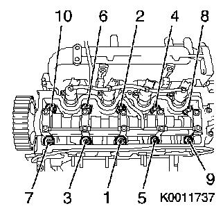
Slacken cylinder head
Important: Undo cylinder head
bolts in the order shown.
|
| • |
Unscrew 10x bolt
|
|
|
|
| 7. |
Remove cylinder head
Note: 2nd mechanic is
required. Lay cylinder head down on wooden blocks. Do not damage
sealing surfaces, valves, injectors or sheathed glow plugs.
|
 Inspect
| 8. |
Clean sealing surface and remove sealant residue
|
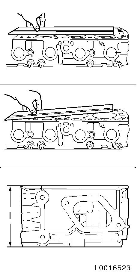
| 9. |
Check cylinder head for sag in length and width on the sealing
surfaces and for distortion along the diagonals
|
| 10. |
Measure height of cylinder head
| • |
Sealing surface to sealing surface (measurement I)
|
|
|
|
| 11. |
Clean sealing surface and remove sealant residue
|
| 12. |
Visually check components
|
| 13. |
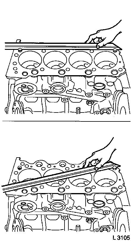
Check for plane surface
| • |
Check cylinder block sealing surfaces for sag in length and
width and for distortion along the diagonals
| – |
With straight edge and feeler gauge
|
|
|
|
|
| 14. |
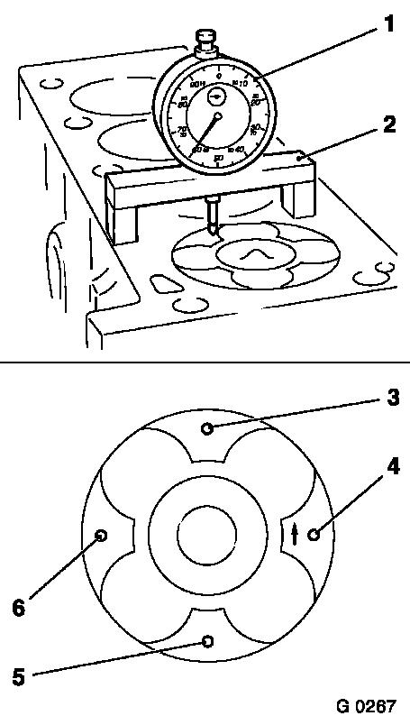
Adjust ignition TDC of cylinder 1
| • |
Use MKM-571-B (1), KM-301 (2)
|
| • |
Insert MKM-571-B in KM-301
|
| • |
Place KM-301 with MKM-571-B on cylinder block
|
| • |
Place probe of MKM-571-B on piston
head
|
| • |
Turn engine in direction of rotation
Note: Determine highest
point of cylinder 1 by turning the crankshaft.
|
|
| 15. |
Measure piston projection
| • |
Place probe of MKM-571-B on cylinder
block
|
| • |
Measure piston projection
| – |
Measure on all 4 pistons
|
| – |
Perform measurements at two different points (3 and 4) or )5
and 6)
|
| – |
Determine highest point by turning the crankshaft
|
|
|
|
|
 Install
Important: Set crankshaft to
approx 60° before cylinder 1 TDC
|
| 16. |
Turn crankshaft
|
Important: The largest piston
projection is decisive for the selection of the cylinder head
gasket with the corresponding marking
|
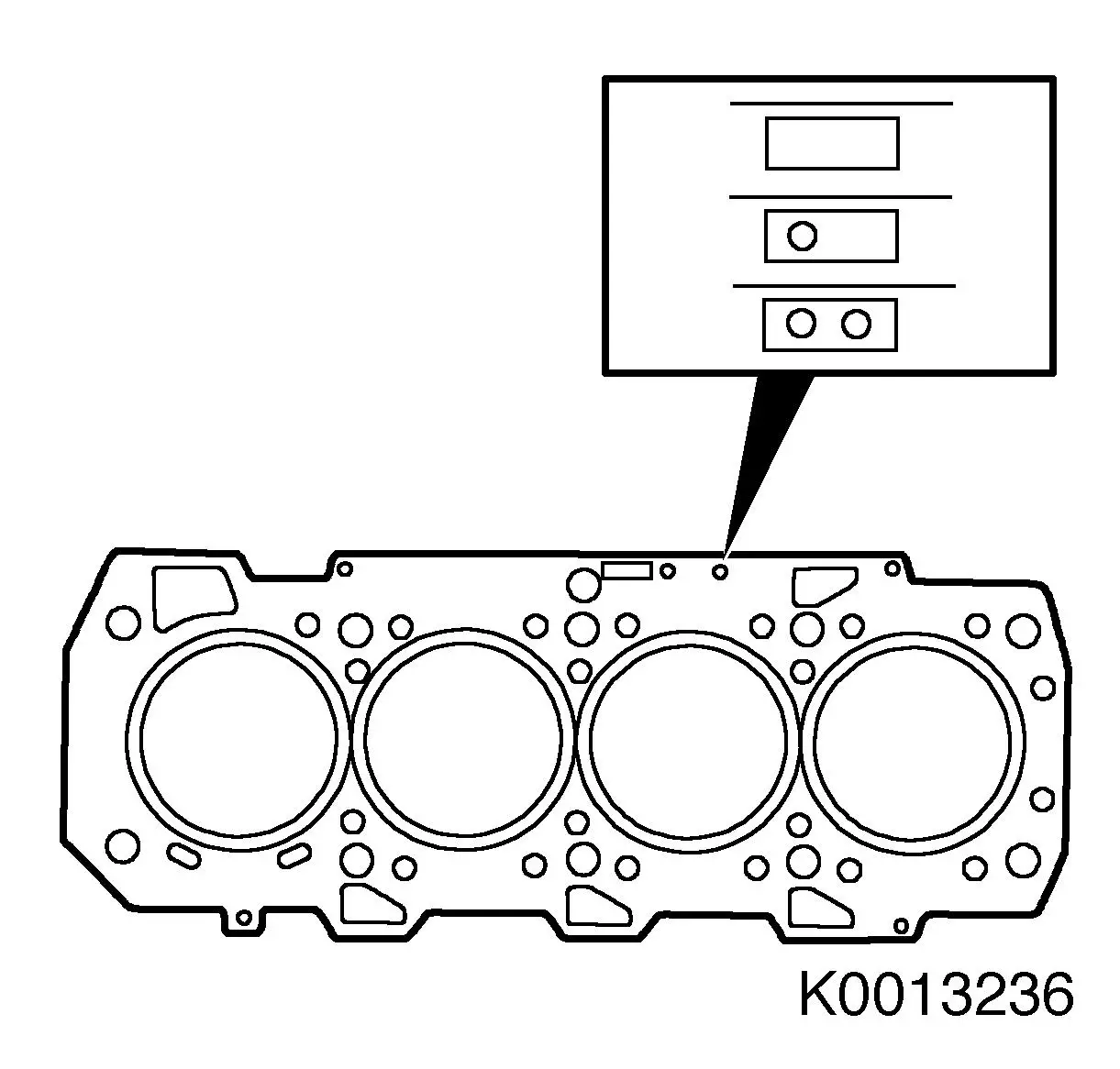
| 17. |
Replace cylinder head gasket
|
Piston projection
|
Thickness of cylinder head gasket
|
Identification
|
|
0.020 - 0.100 mm
|
0.77 - 0.87 mm
|
without hole
|
|
0.101 - 0.200 mm
|
0.87 - 0.97 mm
|
one hole
|
|
0.201 - 0.295 mm
|
0.97 - 1.07 mm
|
two holes
|
| • |
Place cylinder head gasket in position
|
|
|
|
| 18. |
Place cylinder head gasket in position
Note: "TOP" marking
must be on top.
|
| 19. |
Install cylinder head
Note: 2nd mechanic is
required. Note guide sleeves
|
| 20. |
Fasten cylinder head
| • |
Tighten 10x new bolt 65 Nm + 90° +
90° + 90°
Note: Initially tighten
cylinder head to 20 Nm following
tightening sequence (1-10). Torque serves to fix cylinder head to
engine block.
|
|
|
|
| 21. |
Clean sealing surface
|
| 22. |
Install cylinder head cover
| • |
Tighten 7x bolt in a spiral from the inside outward 10 Nm
|
|
| 23. |
Attach 2x hose to cylinder head cover
|
| 24. |
Attach wiring harness
| • |
Connect 5x wiring harness plug
| – |
Pre-catalytic converter temperature sensor
|
|
|
| 25. |
Install intake manifold
|
| 26. |
Install exhaust manifold with turbocharger
| • |
with automatic transmission
|
| • |
with manual transmission
|
|
|
