|
Cylinder Head, Remove and Install (Z16XEP)
 Remove Remove
| 2. |
Disconnect earth connection from battery
|
| 3. |
Remove air cleaner housing - Z16XEP 
|
| 4. |
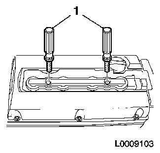
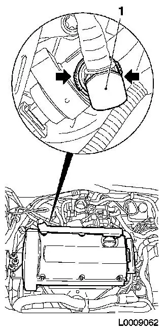
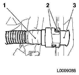
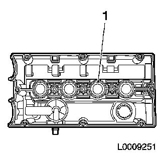
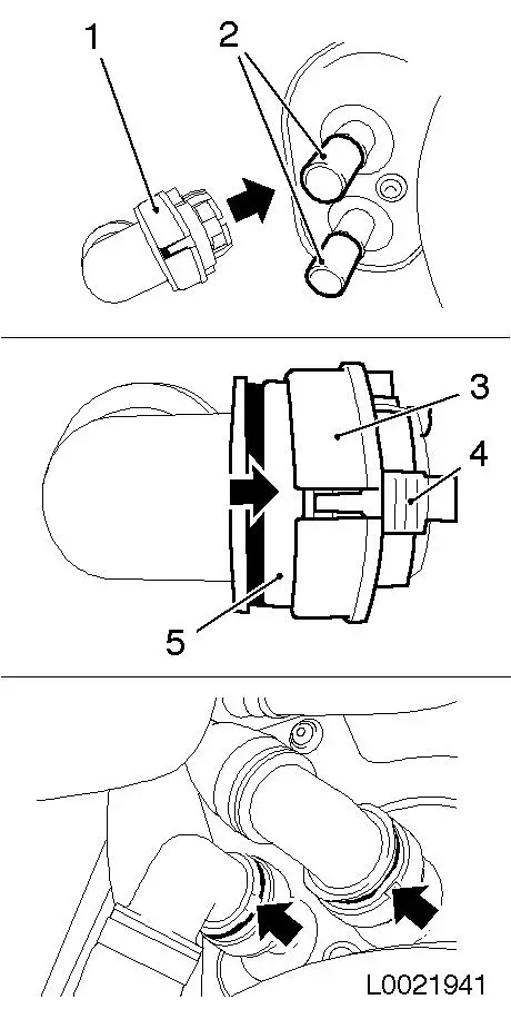
Remove DIS-ignition module
| • |
Remove cover of DIS-ignition module in the direction of the
arrow
Note: Note arrow on
cover
|
| • |
Detach from spark plugs using KM-6009
(1)
|
|
|
|
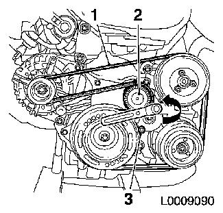
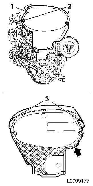
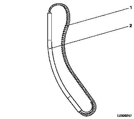
| 5. |
Detach ribbed V-belt (1)
| • |
Mark direction of rotation
|
| • |
Apply tension to ribbed V-belt tensioner (2) in the direction
of the arrow and fix with KM-6130 (3)
|
|
|
|
| 6. |
Raise vehicle by its full height
|
| 7. |
Place collecting basin underneath.
|
| 8. |
Drain coolant
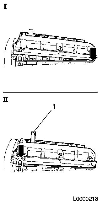
| • |
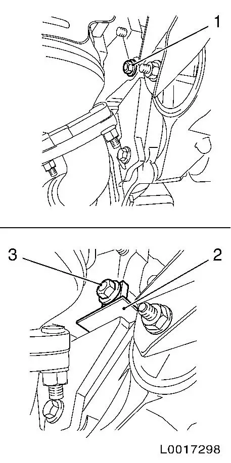
Open drain bolt on radiator
|
|
| 9. |
Detach the lower engine cover and lower engine splash guard
|
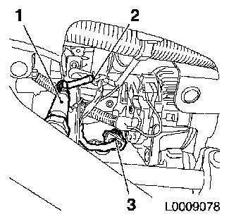
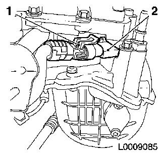
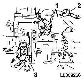
| 10. |
Expose wiring harness for catalytic converter control oxygen
sensor (1)
| • |
Disconnect wiring harness connector (3)
|
|
|
|
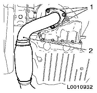
| 11. |
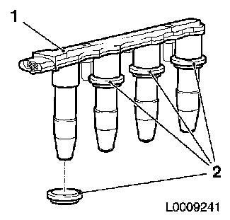
Detach front exhaust pipe (2) from catalytic converter
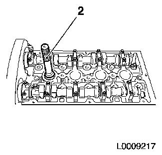
|
|
|
| 12. |
Remove gasket and clean sealing surface
|
| 13. |
Detach intake manifold support (3) from cylinder block
|
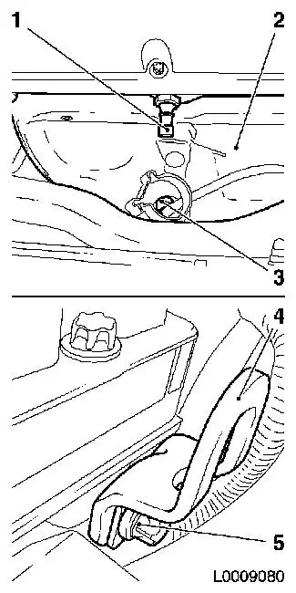
| 14. |
Disconnect wiring harness plug (5) from tank vent valve (4)
|
|
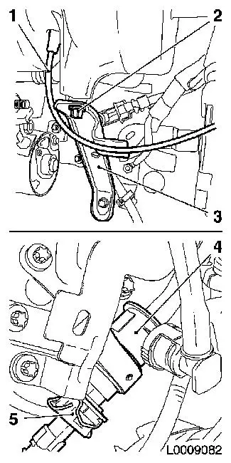
|
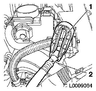
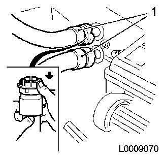
| 15. |
Disconnect tank vent valve hose (1)
| • |
Unlatch tank vent valve hose in the direction of the arrow
|
|
|
|
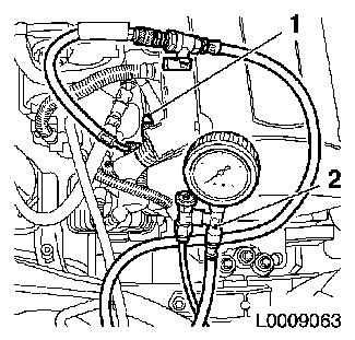
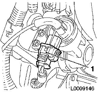
| 16. |
Release fuel pressure via test connection (1) using KM-J-34730-91 (2)
| • |
Collect exiting fuel in a suitable container - observe safety
regulations and national legislation
|
|
|
|
| 17. |
Detach fuel line (2) from fuel rail
| • |
Disconnect with KM-796-A (1)
|
|
|
|
| 18. |
Detach coolant hose (2) from throttle valve body (1)
|
|
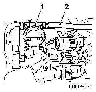
|
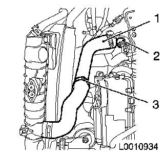
| 19. |
Disconnect coolant hoses from heater core
| • |
Detach 2x coolant hoses (1)
| – |
Detach in direction of arrow
|
|
|
|
|
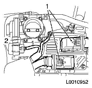
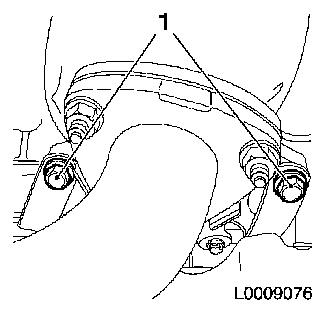
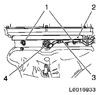
| 20. |
Detach engine wiring harness from engine control unit
| • |
Disconnect 2x wiring harness plug, engine control unit (1)
|
|
|
|
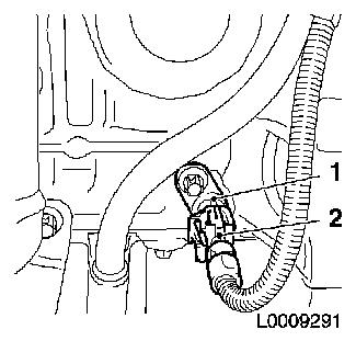
| 21. |
Disconnect wiring harness plug (1) from intake pipe pressure
sensor (2)
|
|
|
| 22. |
Disconnect camshaft sensor wiring harness plug
|
| 23. |
Disconnect wiring harness plug, PDA system vacuum unit (1)
|
|
|
| 24. |
Disconnect thermostat wiring harness plug (1)
|
| 25. |
Disconnect wiring harness plug for coolant temperature sensor
(3)
|
| 26. |
Disconnect wiring harness plug of EGR valve (4)
|
|
|
| 27. |
Disconnect wiring harness plug (2) of crankshaft pulse pick-up
(1)
|
|
|
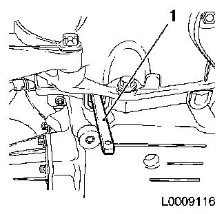
| 28. |
Remove brake force amplifier vacuum line (1)
|
| 29. |
Disconnect throttle valve body wiring harness plug (2)
|
|

|
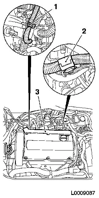
| 30. |
Expose engine wiring harness
| • |
Open 2x clip (1) and (2)
|
| • |
Unclip wiring trough (3)
| – |
Set engine wiring harness aside
|
|
|
|
|
| 31. |
Detach engine vent pipe (1) from cylinder head cover (3)
|
|
|
| 32. |
Detach front toothed belt cover (top) (1)
| • |
Release upper catch (3)
|
| • |
Pull front toothed belt cover (top) upwards by cast projection
(arrow), applying slight tension
|
|
|
|
| 33. |
Raise vehicle by its full height
|
| 34. |
Detach catalytic converter support
|
|
|
| 35. |
Possibility 1: Lock flywheel
|
|
|
| 36. |
Possibility 2: Lock crankshaft
| • |
Attach KM-6625
| – |
Detach screwed connection (1)
|
| – |
Tighten screwed connection (3)
|
|
|
|
|
| 37. |
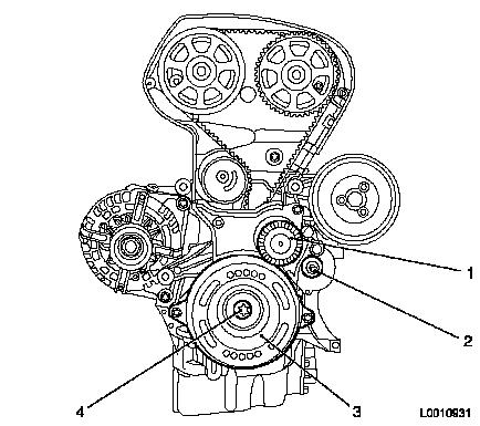
Detach torsional vibration damper (3)
|
| 38. |
Detach ribbed V-belt tensioner (1)
| • |
Unscrew bolt (2)
| – |
Ribbed V-belt tensioner remains locked with KM-6130
|
|
|
|
|
| 39. |
Detach front toothed belt cover (bottom) (2)
|
|
|
| 40. |
Set engine to TDC
| • |
Remove KM-911 or KM-6625
|
| • |
Screw in bolt, torsional vibration damper
|
| • |
Move crankshaft in direction of engine rotation to "cylinder 1
TDC of combustion stroke" (III)
|
|
| 41. |
Lower vehicle by its full height
|
| 42. |
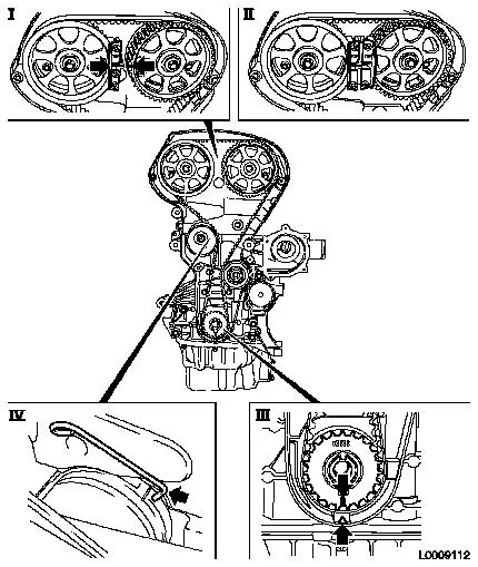
Lock camshaft sprockets in position with KM-6340
| • |
Position camshaft sprockets in such a way that the markings
(arrows) are opposite each other
|
| • |
Attach KM-6340-Left to intake
camshaft sprocket (I)
|
|
| 43. |
Remove toothed belt
| • |
Mark direction of rotation
|
| • |
Apply tension to toothed belt tension roller clockwise, using
an Allen key and fix using KM-6333
(IV)
|
|
|
|
| 44. |
Detach lower coolant hose (1) from thermostat housing (2)
|
|
|
| 45. |
In design with oil pressure switch on cylinder head: Remove
cover (2)
| • |
Disconnect wiring harness plug, cylinder head oil pressure
switch (4)
| – |
Unclip wiring harness, cylinder head oil pressure switch
(3)
|
|
|
|
|
| 46. |
For design with cylinder head oil pressure switch: Remove
cylinder head oil pressure switch (1)
|
| 47. |
Remove mixture regulator oxygen sensor (3)
| • |
Unclip wiring harness plug for mixture regulator oxygen
sensor
| – |
Disconnect wiring harness connector.
|
|
|
| 48. |
Remove engine transport shackle (4)
|
| 49. |
Detach heat shield (2) from exhaust manifold
|
|
|
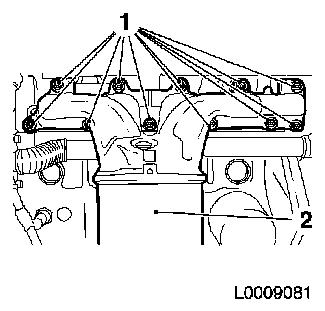
| 50. |
Detach exhaust manifold (2) from cylinder head
|
|
|
| 51. |
Remove exhaust manifold gasket
|
| 52. |
Clean sealing surfaces.
|
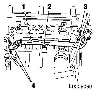
| 53. |
Remove coolant pipe (1)
| • |
Unscrew 5x bolts (2), (3) and (4)
|
|
|
|
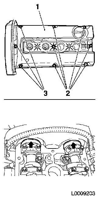
| 54. |
Detach cylinder head cover (1)
| • |
Unlatch and remove engine vent pipe
|
| • |
Slacken 3x bolt (3) pull upwards and fix in this position with
adhesive tape
|
| • |
Slacken 6x bolts (2)
Note: Care should be
taken that the area of the front camshaft bearing caps (arrows) is
clean and free from remains of sealant
|
|
|
|
Important: Remove cylinder head
only when engine is cold (room temperature)
|
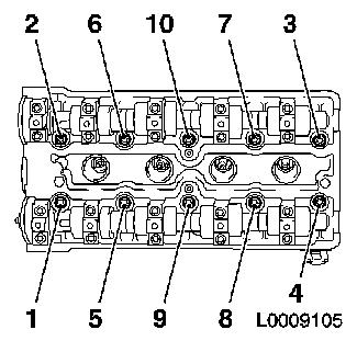
| 55. |
Remove cylinder head
| • |
Unscrew 10x bolt
Note: Unfasten bolts in
the order shown
|
|
|
|
| 56. |
Remove cylinder head
Note: Second
mechanic
| • |
Lay cylinder head on suitable base
|
| • |
Remove cylinder head gasket
|
|
| 57. |
Clean sealing surfaces.
|
| 58. |
Cylinder Head, Check for Plane Surface
|
 Install
| 59. |
Position cylinder head
| • |
Install cylinder head gasket
Note: Second
mechanic
|
Important: Check installation
position
|
| • |
Position cylinder head
|
|
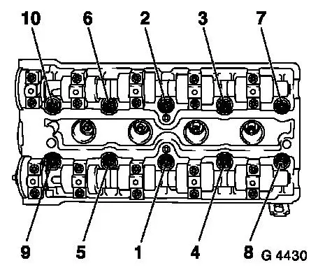
| 60. |
Install cylinder head
| • |
Tighten 10x bolt 25 Nm + 90° +
90° + 90° + 45°
Note: Note correct
tightening sequence
| – |
Use new cylinder head bolts
|
|
|
|
|
| 61. |
Replace gasket, cylinder head cover
| • |
Insert new gasket (1) in cylinder head cover
|
|
|
|
| 62. |
Remove spark plug, cylinder 1 with KM-6363
|
| 63. |
Install KM-6354 (1) in spark plug
thread, cylinder 1
|
|
|
Important: When assembling the
cylinder head, care must be taken that the cylinder head cover
gasket does not become detached.
An incorrectly fitted cylinder head cover gasket can lead to
serious damage to the engine
|
| 64. |
Place cylinder head cover in position
| • |
Lift cylinder head cover via KM-6354
|
| • |
Position cylinder head cover at the rear (i)
|
| • |
Press cylinder head cover carefully downwards at the back
(II)
|
|
|
|
| 65. |
Attach cylinder head cover
| • |
Remove adhesive tape from 3 bolts
|
| • |
Attach engine vent pipe and latch
|
|
| 66. |
Install DIS ignition module (1)
| • |
Attach DIS ignition module cover
|
|
|
|
| 68. |
Install exhaust manifold gasket
| • |
Observe correct fitting position
|
|
| 69. |
Attach exhaust manifold to cylinder head.
Note: Tighten nuts in a
spiral, working from inside to outside
|
| 71. |
Attach heat shield to exhaust manifold
|
| 72. |
Fit engine transport shackle
|
| 73. |
Install oxygen sensor mixture regulator
| • |
Coat mixture regulator oxygen sensor with special grease
|
| • |
Screw in mixture regulator oxygen sensor 40 Nm
|
| • |
Fix wiring harness plug
|
| • |
Lay mixture regulator oxygen sensor wiring harness
|
|
| 74. |
For design with oil pressure switch in cylinder head: install
cylinder head oil pressure sensor with new gasket 20 Nm
|
| 75. |
In design with oil pressure switch in cylinder head: Remove
cover
| • |
Connect wiring harness plug of oil pressure sensor
| – |
Lay wiring harness, oil pressure sensor
|
|
|
| 76. |
Insert toothed belt
Note: Threading the
toothed belt through the engine damping block support is only
permissible in conjunction with the assembly tool supplied with new
toothed belts as otherwise it is possible to damage the toothed
belt at this stage by kinking it
| • |
Insert toothed belt (1) in enclosed assembly tool (2)
| – |
If the toothed belt has been used, observe direction of
rotation
|
|
| • |
Guide toothed belt through engine damping block support with
assembly tool
|
|
|
|
| 77. |
Position toothed belt
Note: If the toothed
belt has been used, observe direction of rotation
| • |
Place toothed belt on exhaust camshaft sprocket
|
| • |
Place toothed belt on intake camshaft sprocket
|
| • |
Guide toothed belt past the tensioning and guide rollers and
place on toothed belt drive gear
|
| • |
Apply tension to the toothed belt tension roller and remove
KM-6333
|
|
| 79. |
Raise vehicle by its full height
|
| 80. |
Turn crankshaft through 720°
| • |
2 revolutions in direction of engine rotation
|
| • |
Place toothed belt drive gear on the marking, cylinder 1 TDC of
combustion stroke
|
|
| 81. |
Lower vehicle by its full height
|
| 82. |
Lock camshaft sprockets in position with KM-6340
| • |
Insert KM-6340-Right
Note: Markings on
camshaft sprockets must align - otherwise dismantle toothed belt
and place in position again
|
|
| 84. |
Raise vehicle by its full height
|
| 85. |
Attach front toothed belt cover (bottom)
|
| 86. |
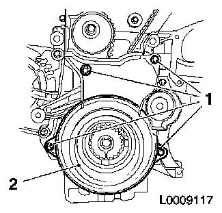
Remove bolt on torsional vibration damper
| • |
Lock flywheel with KM-911 or KM-6625
|
|
| 87. |
Fit torsional vibration damper
Important: Use new bolt
|
| • |
Tighten bolt 95 Nm + 45° +
15°
|
|
| 88. |
Possibility 1: Remove KM-911
|
| 89. |
Possibility 2: Detach KM-6625
| • |
Detach screwed connection
|
| • |
Tighten bolted connection
|
|
| 90. |
Attach ribbed V-belt tensioner
|
| 91. |
Insert ribbed V-belt
Note: Observe direction
of rotation
| • |
Apply tension to ribbed V-belt tensioner anti-clockwise and
place ribbed V-belt in position
|
|
| 92. |
Attach the lower engine cover and right engine splash guard
|
| 93. |
Attach catalytic converter support to catalytic converter
|
| 94. |
Attach intake manifold support to cylinder block
| • |
Connect tank vent valve wiring harness plug
|
|
| 95. |
Attach front exhaust pipe to exhaust manifold
|
| 96. |
Lower vehicle by its full height
|
| 97. |
Attach engine vent pipe to cylinder head cover
|
| 98. |
Attach engine wiring harness
| • |
Fix wiring harness plug
| – |
Throttle valve body, crankshaft pulse pick-up, EGR valve,
coolant temperature sensor, thermostat, PDA-system, camshaft
sensor, intake pipe pressure sensor, engine control unit
|
|
| • |
Attach wiring trough, injectors
|
| • |
Clip wiring harness into mountings
|
|
Important: Ensure that it is
latched correctly
|
| 99. |
Attach front toothed belt cover (top)
|
Important: It is imperative to
adhere to the following assembly order
|
| 100. |
Attach cooling hoses to heater core
| • |
Fit 2x quick release fittings (1) onto heater core connection
port (2) as far as they will go
Note: Pay attention to
coloured markings
|
| • |
Slide the 2x quick-release fitting catches (3) in the direction
of the arrow all the way to the stop by simultaneously pressing the
release buttons (4)
| – |
The colour rings (5) must be visible
|
|
| • |
Check that quick release fittings are correctly seated and that
the colour rings (5) are visible
|
|
|
|
| 101. |
Attach lower coolant hose to thermostat housing
|
| 102. |
Attach coolant hose, throttle valve body
|
| 103. |
Attach fuel line to fuel rail
|
| 104. |
Remove air cleaner housing - Z16XEP
|
| 105. |
Attach earth connection to battery
|
| 106. |
Top up coolant, correct if necessary
|
| 107. |
Program volatile memories
|
|
