|
Test battery/alternator
The following table provides an overview of the alternator check
procedure.
Battery check
1.) Measure off-load voltage
- Voltage measurement at battery terminal 30 and battery terminal
31.
| |
Off-load voltage, reference value:
|
12,8 - 13,2 V
|
| |
Reference value not attained:
|
Charge or replace battery
|
2.) Battery Test:
- Test battery with tester KM-J-42000
Alternator check
3.) Visual testing:
- Connect battery to supply system
- Ensure V-belt tension complies with auto manufacturer data
4.) Measure no-load control voltage
- Start cold engine (no consumers)
- Engine speed 2000 rpm
- Measure control voltage at alternator connection B+ and
alternator housing (not at battery terminals)
| |
Control voltage, reference value:
|
13,7 - 14,8 V
|
| |
Reference value not attained:
|
Vehicle with petrol engine: continue with test step 5
|
| |
|
Vehicle with diesel engine: continue with test step 7
|
| |
Reference value attained:
|
continue with test step 9
|
5.) Test preexciting circuit:
- Remove terminal L wiring harness plug
- Voltage measurement at terminal L and battery terminal 31
- Ignition ON
- Engine OFF
| |
Voltage, reference value:
|
less than 5 V
|
| |
Reference value not attained:
|
- test wiring harness between alternator terminal L and engine
control unit for short-circuit against voltage, earth and break
|
| |
|
or
|
| |
|
- replace engine control unit
|
Important:
Components must be replaced in the specified sequence.
| |
Reference value attained:
|
continue with test step 6
|
6.) Preexciting circuit:
- Connect terminal L wiring harness plug
- Voltage measurement (with adapter cable) at terminal L and
battery terminal 31
- Engine RUNNING
- switch on consumer (lights, heated rear window, heater fan,
etc.)
| |
Voltage, reference value:
|
greater than 5 V
(depending on engine speed and output of the
connected consumer)
|
| |
Reference value not attained:
|
- test wiring harness between alternator terminal L and engine
control unit for short-circuit break
|
| |
|
or
|
| |
|
- replace engine control unit
|
Important:
Components must be replaced in the specified sequence.
| |
Reference value attained:
|
- replace alternator control unit (if control unit is listed
separately according to EPC)
|
| |
|
or
|
| |
|
- Replace alternator
|
Important:
Components must be replaced in the specified sequence.
7.) Test preexciting circuit:
- Remove terminal L, F wiring harness plug
- Voltage measurement at terminal L, F and battery terminal
31
- Ignition ON
- Engine OFF
| |
Voltage reference value, terminal L:
|
greater than 8 V
|
| |
Voltage reference value, terminal F:
|
less than 5 V
|
| |
Reference value not attained:
|
test wiring harness between alternator terminal L, F and engine
control unit for short-circuit against voltage, earth and break
|
| |
|
or
|
| |
|
- engine control unit
|
Important:
Components must be replaced in the specified sequence.
8.) Test preexciting circuit:
- Connect terminal L, F wiring harness plug
- Voltage measurement (with adapter cable) at terminal L, F and
battery terminal 31
- Engine RUNNING
- switch on consumer (lights, heated rear window, heater fan,
etc.)
| |
Voltage reference value, terminal L:
|
greater than 5 V
(depending on engine speed and output of the
connected consumer)
|
| |
Voltage reference value, terminal F:
|
greater than 5 V
|
| |
Reference value not attained:
|
- test wiring harness between alternator terminal L, F and
engine control unit for break
|
| |
|
or
|
| |
|
- replace engine control unit
|
Important:
Components must be replaced in the specified sequence.
| |
Reference value attained:
|
- replace alternator control unit (if control unit is listed
separately according to EPC)
|
| |
|
or
|
| |
|
- Replace alternator
|
Important:
Components must be replaced in the specified sequence.
9.) Alternator charge testing:
- Position clamp-on ammeter as close to alternator B+ connection
as possible
- Measure control voltage at battery terminal 30 and battery
terminal 31
- Start engine
- Engine speed approx. 2000 rpm
- Charge the supply system (battery) with 50 % of the current
strength specified on the rating plate.
Example: for an 80 amp (A) alternator, the following consumers
would be switched on to achieve a charge of 40 A:
| |
Lights:
|
approx. 12 A
|
| |
Heated rear window:
|
approx. 10 A
|
| |
Fog lights:
|
approx. 8 A
|
| |
Interior fan:
|
approx. 8 A
|
| |
Air-conditioning unit:
|
approx. 8 A
|
| |
Total:
|
approx. 46 A
|
- Here, the control voltage must not fall more than 0.5 V below
the reference value.
| |
Control voltage, reference value:
|
13,7 - 14,8 V
|
| |
Reference value not attained:
|
continue with test step 10
|
| |
Reference value attained:
|
see instruction for static current measurement
|
10.) Charge test 1, charging current circuit:
- Connect bridge cable between battery terminal 31 and alternator
housing:
- Control voltage at battery terminal 30 and battery terminal
31
- Here, the control voltage must not fall more than 0.5 V below
the reference value.
| |
Control voltage, reference value:
|
13,7 - 14,8 V
|
| |
Reference value not attained:
|
continue with test step 11
|
| |
Reference value attained:
|
High contact resistance between battery terminal 31 and
alternator housing
|
11.) Charge test 2, charging current circuit
- Connect bridge cable between battery terminal 30 and B+:
- Measure control voltage at battery terminal 30 and battery
terminal 31
- Here, the control voltage must not fall more than 0.5 V below
the reference value.
| |
Control voltage, reference value:
|
13,7 - 14,8 V
|
| |
Reference value not attained:
|
Replace alternator
|
| |
Reference value attained:
|
High contact resistance between battery terminal 31 and
alternator housing
|
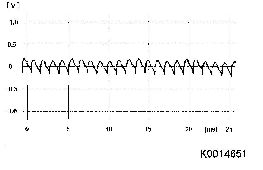
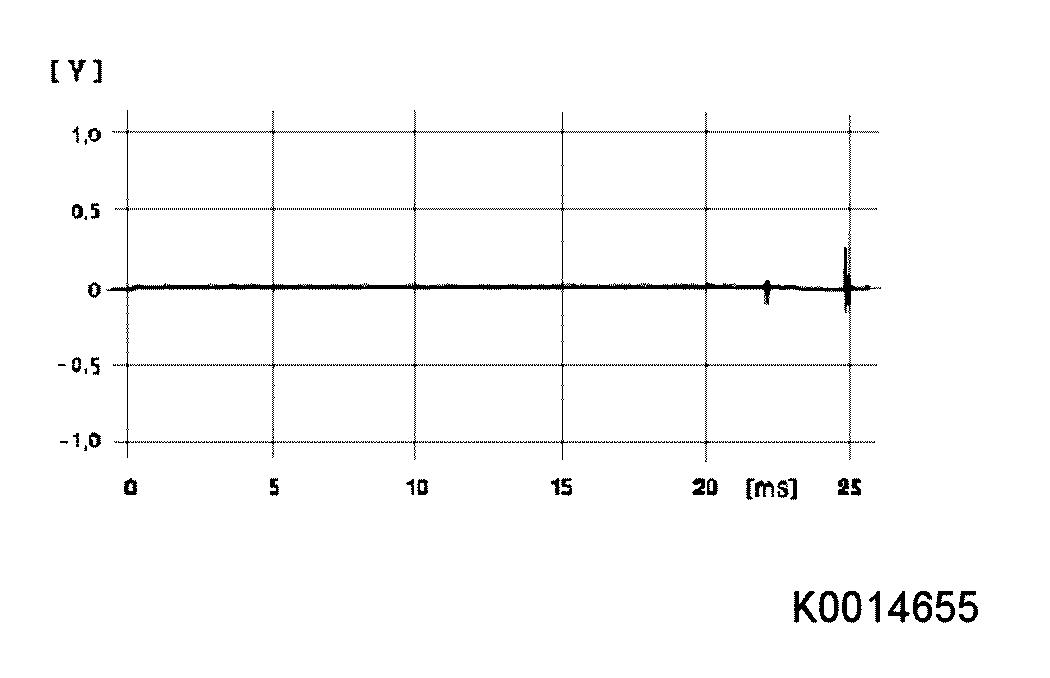
Oscilloscope - reference images:
- Test alternator with oscilloscope (connect as for voltage
measurement to B+ and alternator housing)
|
|
Alternator without error
|
|
|
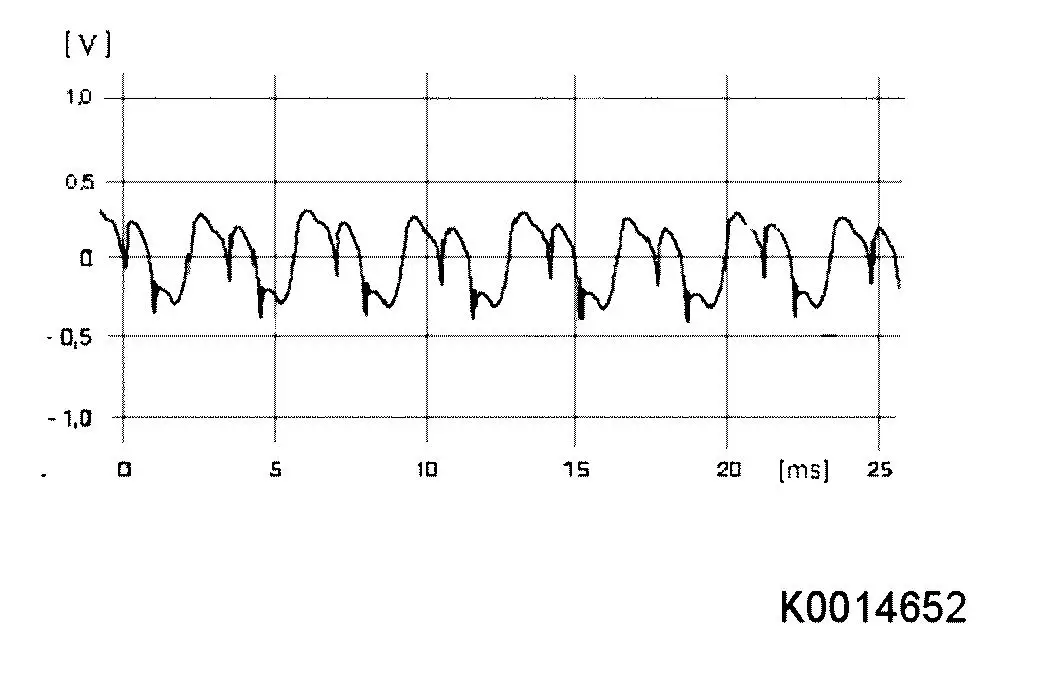
Alternator with phase error
|
|
|
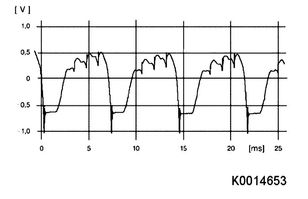
Alternator with diode error (plus or minus diode break)
|
|
|
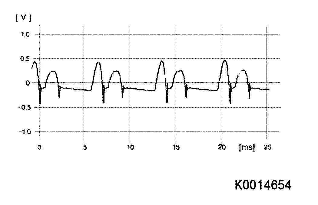
Alternator with diode error, plus or minus diode (short-circuit
- alternator excited)
|
|
|
Alternator with diode error, plus or minus diode (short-circuit
- alternator not excited)
|
Instruction for static current measurement:
Unpermissibly high battery discharge may also
result from drawing of an increased static current.
- Drawing of the static current is dependent on:
| |
- vehicle equipment
|
| |
- control unit tracking time
|
|
