|
Replace electronic control unit (AF40)
Important: If the
automatic transmission or Transmission Control Module (TCM) is
replaced, the Transmission Control Module (TCM) software is
overwritten and the basic settings must be reset. This is done on a
long test drive when the automatic transmission is warm by changing
through all gears several times while "D" is engaged. After the
long test drive, it may be possible that the Transmission Control
Module (TCM) might not be completely finished with the running-in
process. Thus, the customer must be informed that until the
running-in process is complete, the transmission may not change
gears or operate optimally. Until the running-in process is
complete, there could be hard, jerky gearchanges, increased engine
speed during gearchanges and delayed gearchanges.
 Remove Remove
| 1. |
When replacing the transmission control module, carry out
"Reset" with TECH 2 before removal 
|
| 2. |
Remove battery support
|
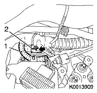
| 3. |
Detach wiring harness for preheating period control unit (1)
from battery support
| • |
Unclip wiring harness plug
|
|
| 4. |
Disconnect wiring harness plug of Transmission Control Module
(2)
| • |
Release wiring harness plug (arrow) and disconnect
|
|
|
|
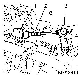
| 5. |
Detach selector lever actuation cable (2)
| • |
Unclip ball socket (3) from actuation lever (4)
|
| • |
Unclip from counterhold
Note: Pull back sleeve
(1) and pull cable from counterhold.
|
|
|
|
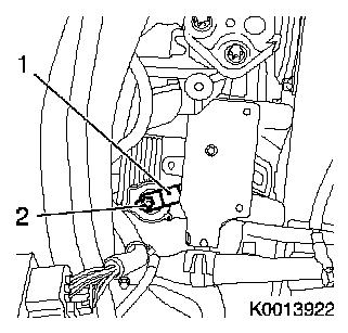
| 6. |
Detach actuation lever (1)
|
|
|
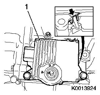
| 7. |
Detach control unit (1)
Important: Do not damage plug
pins.
|
| • |
Carefully pull control unit upward
|
|
|
|
 Install
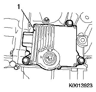
| 8. |
Attach control unit (1)
| • |
Set selector lever shaft and control unit in position "N"
| – |
Pivot selector lever shaft all the way forward with actuation
lever and then move back two notches
|
| – |
Align marks on control unit
|
|
Important: do not damage plug
pins. Check for correct seating of the control unit (arrow).
|
| • |
Insert control unit
|
|
|
|
| 9. |
Attach actuation lever (1)
|
|
|
| 10. |
Attach selector actuation cable (2)
| • |
Clip cable into counterhold
Note: Pull sleeve (1)
back and clip in cable.
|
| • |
Clip ball socket (3) to actuation cable (4)
|
|
|
|
| 11. |
Connect wiring harness plug of Transmission Control Module
(2)
| • |
Connect and latch wiring harness plug (arrow)
|
|
| 12. |
Connect wiring harness of preheating period control unit (1) to
battery support
|
|
|
| 13. |
Install battery.
| • |
Install battery support
|
|
| 14. |
When replacing the transmission control module, carry out
"Program" with TECH 2 after installation
| • |
Save position "N" in control unit
|
|
| 15. |
Program volatile memories
|
|
