Drivetrain and Front Suspension Frame Replacement
Special Tools
| • |
CH 49289
Centering Frame |
For equivalent regional tools, refer to
Special Tools .
Removal Procedure
| 1. |
Support the radiator and
condenser from above using the condenser tabs on each side.
|
|
Caution: With wheels of the vehicle facing straight ahead, secure
the steering wheel utilizing steering column anti-rotation pin,
steering column lock, or a strap to prevent rotation. Locking of
the steering column will prevent damage and a possible malfunction
of the SIR system. The steering wheel must be secured in position
before disconnecting the following components:
| |
|
• |
The intermediate shaft(s) |
After disconnecting these components, do not
rotate the steering wheel or move the front tires and wheels.
Failure to follow this procedure may cause the SIR coil assembly to
become un-centered and cause possible damage to the SIR coil. If
you think the SIR coil has became un-centered, refer to your
specific SIR coil's centering procedure to re-center SIR
Coil. |
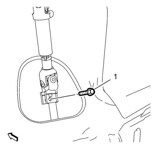
| 2. |
Remove and DISCARD the lower
steering intermediate shaft bolt (1). |
| 3. |
Detach the steering
intermediate shaft from steering gear. |
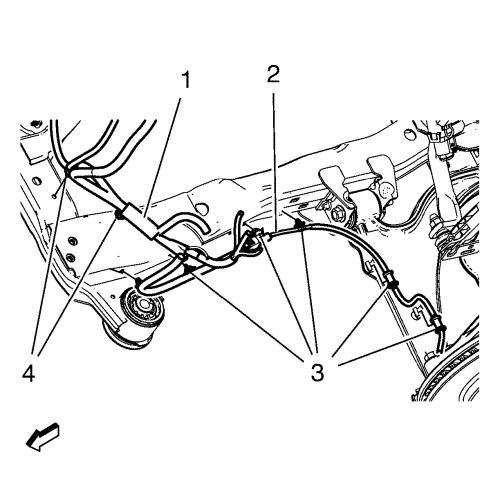
| 10. |
Remove the wheel speed sensor
wiring harness (2) from the frame on both sides. |
| |
Remove the wiring harness retainers (3) from the frame and the
lower control arm. |
| 11. |
Remove the radiator wiring
harness (1) from the frame. |
| |
Remove the wiring harness retainers (4) from the frame. |
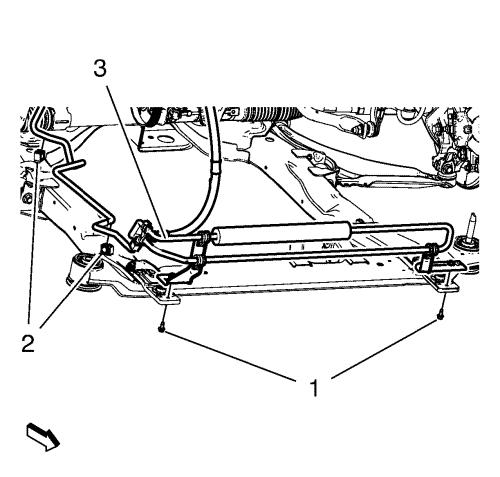
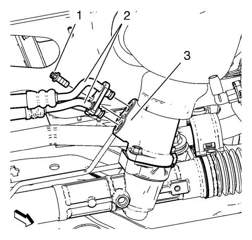
| 12. |
If equipped with hydraulic
power steering, remove the power steering fluid cooling pipe bolt
(1), clip out (2) and securing the power steering fluid cooling
pipe (3) to the vehicle. |
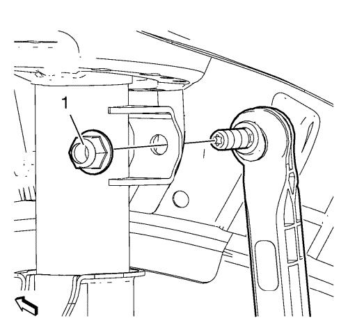
| 14. |
Remove and DISCARD the
stabilizer link nut (1) from the strut. |
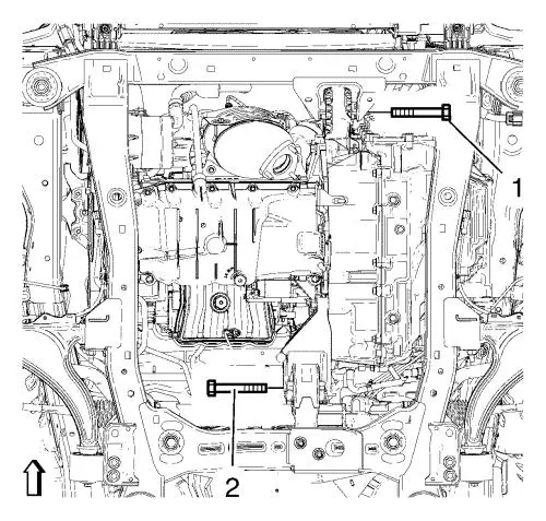
| 16. |
Remove the front (1) and the
rear (2) transmission mount bracket bolts. |
| 17. |
If equipped with hydraulic
power steering, remove the power steering gear inlet and outlet
hose bolts (1). Remove the inlet and outlet hose (2) from the
steering gear (3). |
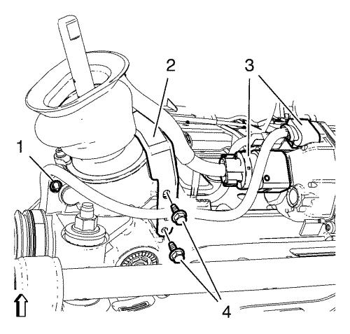
| 18. |
If equipped with electronic
power steering, carefully disconnect 2 wiring harness plugs (3)
from the steering gear with a suitable tool. Use the following
procedure to disconnect the 2 wiring harness plugs: |
| |
18.1 |
Insert a small flat bladed
tool into the pocket of the connector retention feature.
|
| |
18.2 |
Gently move the retention
feature back and pull on the connector to disconnect the
connector. |
| 19. |
Loosen the front bumper energy
absorber bracket bolt. |
|
Note: The SPX
installation manual is supplied with the special tool and is also
available online from SPX directly. Go to
www.spxtools-shop.com.
|
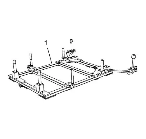
| 20. |
Assemble the CH-49289
centering frame (1) according to the details provided in the
SPX installation manual. |
| 21. |
Support the CH-904
base frame on a jack. |
| 22. |
Support the CH-49289
centring frame on the CH-904 base frame
. |
| 23. |
Install the CH-49289
centring frame according to the details provided in the SPX
installation manual. |
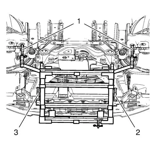
|
Note: Positioning
pins (2, 3) of CH-49289 centring frame MUST stick
into holes of drivetrain frame.
|
| 24. |
Check if wheel alignment is
required. |
| |
Move out position pins (1) and try to insert into underbody
holes. |
|
Note: Simplified
graphic. Suspension frame is supported by centering frame and base
frame.
|
| 25. |
Remove the frame front bolts
(1). |
| 26. |
Remove the frame rear bolts
(2). |
| 27. |
Remove the frame
reinforcements (3). |
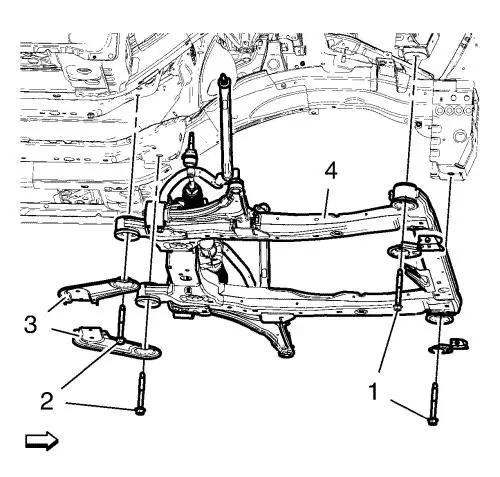
| 28. |
Remove the frame (4) from the
vehicle. |
| 29. |
Remove the following
components if replacing the frame: |
| |
• |
The radiator support
brackets. |
Installation Procedure
| 1. |
Install the following
components on the drivetrain and front suspension frame if
removed: |
| |
• |
The radiator support
brackets. |
|
Note: Positioning
pins (1) of CH-49289 centring frame MUST be
extended in order to guide into underbody holes.
|
|
Note: Simplified
graphic. Suspension frame is supported by centering frame and base
frame.
|
| 2. |
Raise the frame (4) carefully,
using CH 49289 centring frame . |
| 3. |
Install the frame
reinforcements (3). |
| 4. |
Install the frame rear bolts
(2) and tighten to 160 N·m (118 lb ft)
. |
| 5. |
Install the frame front bolts
(1) and tighten to 160 N·m (118 lb ft)
. |
|
Note: The SPX
installation manual is supplied with the special tool and is also
available online from SPX directly. Go to
www.spxtools-shop.com.
|
| 6. |
Lower the CH-49289
centring frame (1) with CH-904 base frame
and a jack. |
| 7. |
Remove the CH-49289
centring frame from the CH-904 base frame
. |
| 8. |
Disassemble the
CH-49289 centering frame (1) according to the
details provided in the SPX installation manual. |
| 9. |
Install and tighten 2 wiring
harness bracket bolts (4) to 9 N·m (80 lb
in) . |
| 10. |
Tighten wiring harness
retainer (1) to steering gear. |
| 11. |
Connect 2 wiring harness plugs
(3). |
| 12. |
Install the front bumper
energy absorber bracket bolt. |
| 13. |
Install the front transmission
mount bolt (1) and tighten to 100 N·m (74 lb
ft) . |
| 14. |
Install the rear transmission
mount bracket bolt (2) and tighten to 100 N·m (74 lb
ft) . |
| 16. |
Install the NEW stabilizer
link nut (1). Tighten the steering linkage tie rod nut to
65 N·m (48 lb ft) . |
| 18. |
If equipped with hydraulic
power steering, install the power steering fluid cooling pipe (3)
to the frame, install the power steering fluid cooling pipe bolt
(1) and clip in (2). Tighten the power steering fluid cooling pipe
bolt to 9 N·m (80 lb in) . |
| 19. |
Install the wheel speed sensor
wiring harness (2) to the frame on both sides. |
| |
Install the wiring harness retainers (3) to the frame and the
lower control arm. |
| 20. |
Install the radiator wiring
harness (1) to the frame. |
| |
Install the wiring harness retainers (4) to the frame. |
| 21. |
If equipped with hydraulic
power steering, install the inlet and outlet hose (2) to the
steering gear (3). |
| 22. |
If equipped with hydraulic
power steering, install power steering gear inlet and outlet hose
bolts (1) and tighten to 11 N·m (97 lb in)
. |
| 23. |
Install the NEW lower steering
intermediate shaft (1) bolt and tighten a first pass to 25
N·m (18 lb ft) . |
| 24. |
Tighten the NEW lower
intermediate steering shaft bolt a final pass to an additional
180 degrees , using the EN-45059
meter . |
| 25. |
Remove the support of the
radiator and condenser. |
| 31. |
Lower the vehicle on a
hoist. |
|
