Front Brake Rotor Replacement
Special Tools
| • |
CH-41013 Rotor
Resurfacing Kit |
| • |
CH-42450-A
Wheel Hub Resurfacing Kit |
For equivalent regional tools, refer to
Special Tools .
Removal Procedure
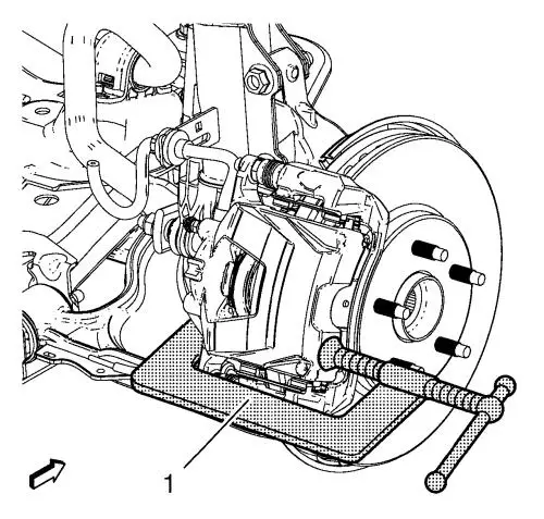
| 3. |
Install a C-clamp (1) over the
body of the brake caliper, with the C-clamp ends against the rear
of the caliper body and the outboard disc brake pad. |
| 4. |
Tighten the C-clamp (1) until
the caliper piston is compressed into the caliper bore enough to
allow the caliper to slide past the brake rotor. |
| 5. |
Remove the C-clamp (1).
|
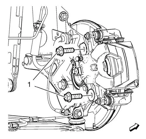
| 6. |
Remove and DISCARD the brake
caliper bracket bolts (1). |
|
Caution: Support the brake caliper with heavy mechanic wire, or
equivalent, whenever it is separated from its mount and the
hydraulic flexible brake hose is still connected. Failure to
support the caliper in this manner will cause the flexible brake
hose to bear the weight of the caliper, which may cause damage to
the brake hose and in turn may cause a brake fluid leak.
|
|
Note: Do NOT
disconnect the hydraulic brake flexible hose from the caliper.
|
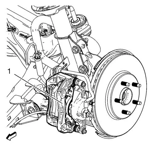
| 7. |
Remove the brake caliper and
the caliper mounting bracket as an assembly (1) from the steering
knuckle and support the assembly with heavy mechanic's wire, or
equivalent. Ensure that there is no tension on the hydraulic brake
flexible hose. |
| 8. |
Mark the position of the brake
rotor to the wheel studs. |
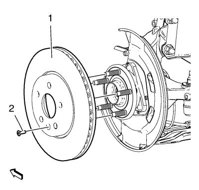
| 9. |
Remove the brake rotor screw
(2). |
| 10. |
Remove the brake rotor (1)
from the wheel hub. |
Installation Procedure
|
Note: Whenever the
brake rotor has been separated from the hub/axle flange, any rust
or contaminants should be cleaned from the hub/axle flange and the
brake rotor mating surfaces. Failure to do this may result in
excessive assembled lateral runout (LRO) of the brake rotor, which
could lead to brake pulsation.
|
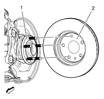
| 1. |
Using the CH-42450-A
resurfacer , thoroughly clean any rust or corrosion from the
mating surface of the hub/axle flange (1). |
| 2. |
Using the CH-41013
resurfacer , thoroughly clean any rust or corrosion from the
mating surface and mounting surface of the brake rotor (2).
|
| 3. |
Inspect the mating surfaces of
the hub/axle flange and the rotor to ensure that there are no
foreign particles or debris remaining. |
| 4. |
Install the brake rotor to the
hub/axle flange. Use the mark made prior to removal to ensure
proper orientation to the flange. |
| 5. |
Install the brake rotor screw
and tighten to 7 N·m (62 lb in) .
|
| 8. |
Remove the support, and
install the brake caliper and the brake caliper bracket as an
assembly to the steering knuckle. |
| 9. |
Install NEW brake caliper
bracket bolts (1) and tighten a first pass to 100
N·m (74 lb ft) . |
| 10. |
Tighten the NEW brake calliper
bracket bolts a final pass to an additional 45 to 60
degrees , using the EN-45059 meter
. |
|
