Front Brake Shield Replacement
Special Tools
EN-45059 Angle Meter
For equivalent regional tools, refer to
Special Tools .
Removal Procedure
|
Caution: Support the brake caliper with heavy mechanic wire, or
equivalent, whenever it is separated from its mount and the
hydraulic flexible brake hose is still connected. Failure to
support the caliper in this manner will cause the flexible brake
hose to bear the weight of the caliper, which may cause damage to
the brake hose and in turn may cause a brake fluid leak.
|
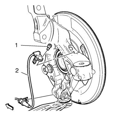
| 3. |
Remove the wheel speed sensor
bolt (1). |
| 4. |
Remove the wheel speed sensor
(2). |
| 5. |
Remove the wheel speed sensor
wiring harness from the steering knuckle. |
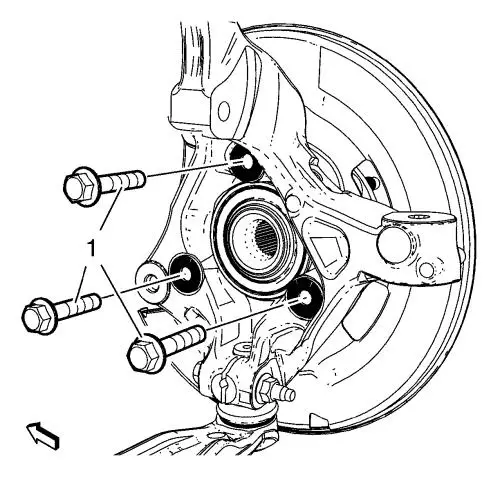
| 7. |
Remove and DISCARD the wheel
bearing/hub mounting bolts (1). |
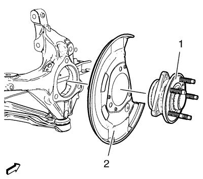
| 8. |
Remove the wheel bearing/hub
(1) and front brake shield (2) from the steering knuckle.
|
Installation Procedure
| 1. |
Position the front brake
shield (2) and wheel bearing/hub assembly (1) in the steering
knuckle. |
|
Caution: This is a self-retaining fastener joint that does not
require thread locking compounds. Do not attempt to clean the
threads with a standard tap. If a standard tap is used, damage to
the joint threads will occur. |
| 2. |
Tighten the bearing/hub bolts
(1) a first pass to 90 N·m (66 lb ft)
. |
| 3. |
Tighten the NEW bearing/hub
bolts (1) a final pass to an additional 60 - 75
degrees , using the EN-45059 meter
. |
| 4. |
Install the wheel speed sensor
wiring harness to the steering knuckle. |
| 5. |
Install the wheel speed sensor
(2). |
| 6. |
Install the wheel speed sensor
bolt (1) and tighten to 6 N·m (53 lb in)
. |
| 9. |
Remove the support and lower
the vehicle. |
|
