Front Wheel Drive Shaft and Intermediate Shaft Assembly
Replacement - Right Side (1.7L Diesel)
Special Tools
| • |
CH-49376
Holding Wrench |
| • |
CH-49400 Hub
Spindle Remover |
For equivalent regional tools, refer to
Special Tools .
Removal Procedure
|
Warning:
To prevent personal injury and/or component
damage, do not allow the weight of the vehicle to load the front
wheels, or attempt to operate the vehicle, when the wheel drive
shaft(s) or wheel drive shaft nut(s) are removed. To do so may
cause the inner bearing race to separate, resulting in damage to
brake and suspension components and loss of vehicle control.
|
|
Caution: Wheel drive shaft boots, seals and clamps should be
protected from sharp objects any time service is performed on or
near the wheel drive shaft(s). Damage to the boot(s), the seal(s)
or the clamp(s) may cause lubricant to leak from the joint and lead
to increased noise and possible failure of the wheel drive
shaft. |
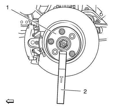
| 3. |
Using the CH-49376
wrench (1) with EN-956-1 extension
(2). |
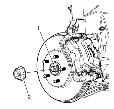
| 4. |
Remove and DISCARD the wheel
drive shaft nut (2) from the wheel drive shaft (1). |
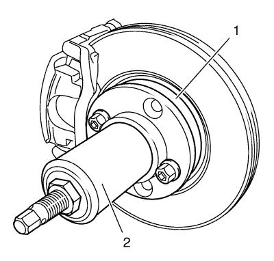
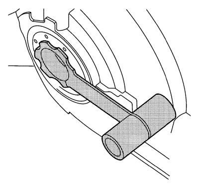
| 5. |
Using the CH-49400
remover (2), separate the brake rotor and wheel bearing/hub
assembly (1). |
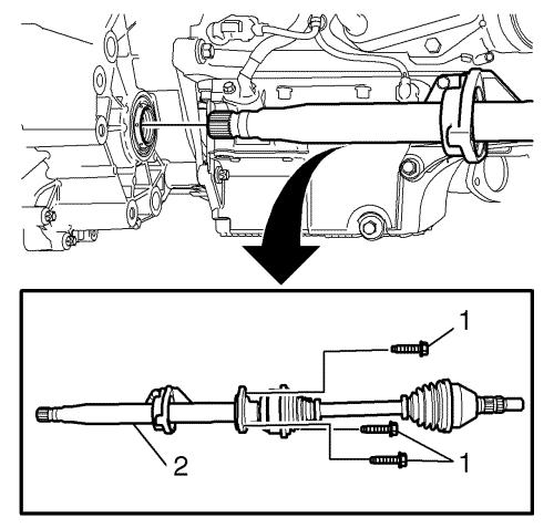
| 8. |
Remove the 3 bolts (1) from
the intermediate flange. |
| 9. |
Remove the wheel drive shaft
and intermediate shaft assembly (2) through bracket. |
Installation Procedure
|
Note: It is not
possible to install the intermediate shaft bearing after the
bonding is made.
|
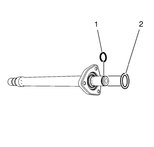
| 2. |
Replace retaining ring
(1). |
| 4. |
Clean the mating faces of the
intermediate shaft and the drive shaft with solvent. |
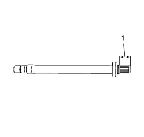
| 5. |
Apply Loctite 262 only to the
drive shaft in the position shown (1). Container and brush have to
be free from metal if used more than once. |
| 6. |
Assemble drive shaft and
intermediate shaft. |
| |
The bonding process takes 12 hours at room temperature. Let the
bonding age either prior reinstallation into the car or after
reinstallation. The car must not be driven or moved during the
aging/bonding. The completed car may be pushed to a parking place
(for aging). |
| 7. |
Install the DT-6332
protector into the differential output shaft seal.
|
| 8. |
Carefully install the
intermediate shaft assembly (2) into the differential until the
splines are past the DT-6332 protector |
| 9. |
Remove the DT-6332
protector from the differential output shaft seal. Install
the intermediate shaft assembly (2) into the differential until it
is fully seated. |
| 10. |
Install the 3 bolts to the
intermediate flange and tighten to 22 N·m (16 lb
ft) . |
| 11. |
Install the front wheel drive
shaft into the front wheel bearing/hub. |
| 14. |
Install the NEW wheel drive
shaft nut (2) on the wheel drive shaft (1) in 3 passes.
|
| 15. |
Using the CH-49376
wrench (1) with EN-956-1 extension
(2). |
| |
• |
Using a torque wrench and the
appropriate size socket (1), tighten the wheel drive shaft nut (2)
to 150 N·m 111 (lb ft) . |
| |
• |
Release the wheel drive shaft
nut (2) trough 45° . |
| |
• |
Retighten the wheel drive
shaft nut (2) to 250 N·m 184 (lb ft)
. |
|
