Engine Control Module Wiring Harness Replacement (LSF without
Start/Stop System)
Removal Procedure
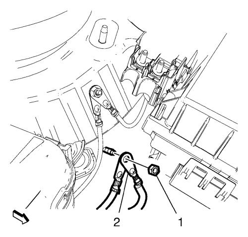
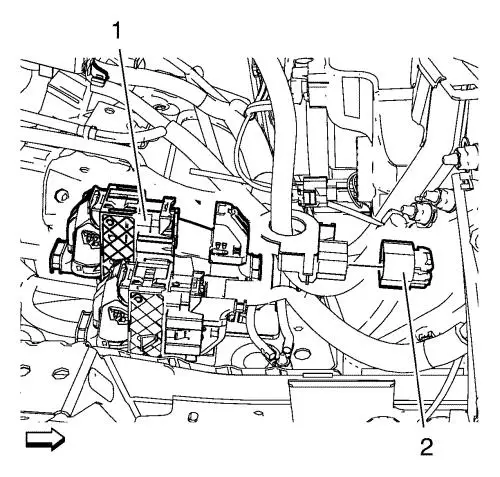
| 5. |
Remove the electronic steering
pump ground cable nut (1). |
| 6. |
Remove the 2 electronic
steering pump ground cables (2). |
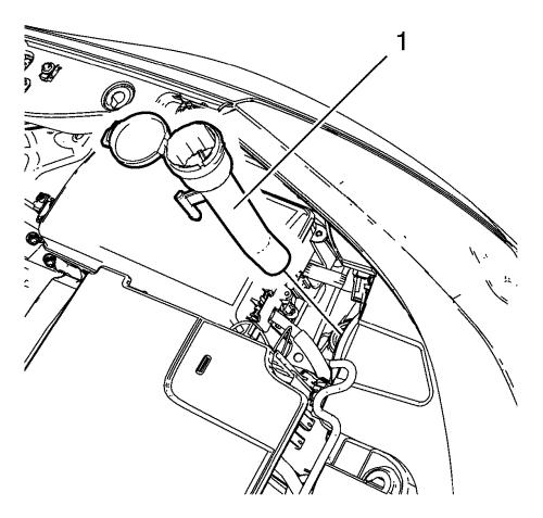
| 7. |
Remove the windshield washer
solvent container filler tube (1). |
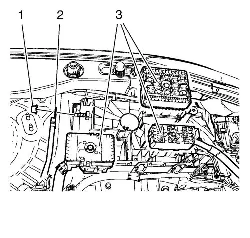
| 8. |
Unclip the 3 wiring harness
plugs (3). |
| 9. |
Disconnect the wiring harness
plug from the front compartment fuse block. |
| 10. |
Remove the 3 ground nuts
(1). |
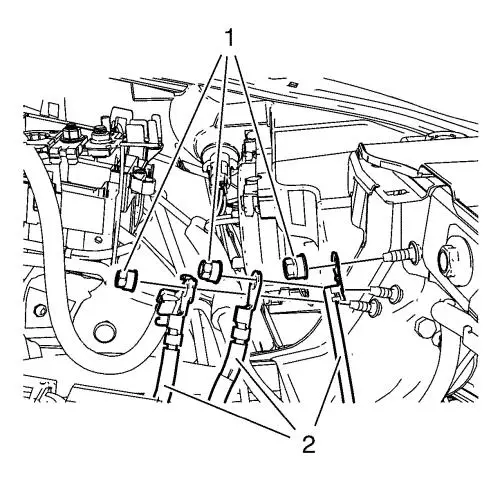
| 11. |
Disconnect the 2 wiring
harness plugs (1, 2). |
| 12. |
Disconnect the positive
crankcase ventilation pipe connector wiring harness plug.
|
| 13. |
Disconnect the oxygen sensor
plug from the engine control module wiring harness. |
| 14. |
Disconnect the air
conditioning compressor wiring harness plug (3). |
| 15. |
Disconnect the exhaust
temperature sensor wiring harness plug (5). |
| 16. |
Unclip the retainer clip (4)
from the exhaust temperature sensor wiring harness bracket.
|
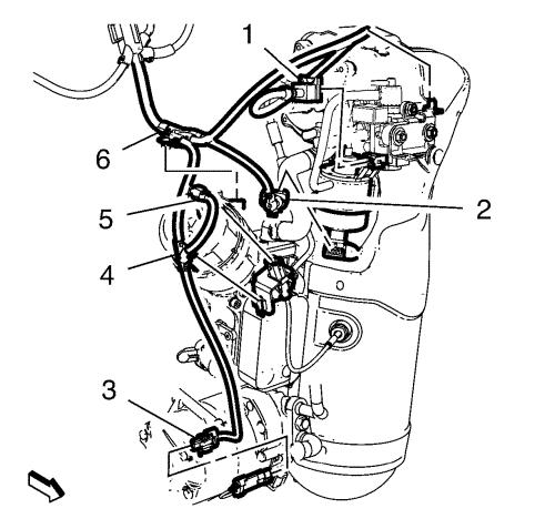
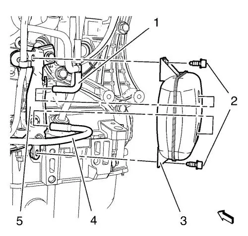
| 17. |
Disconnect the turbocharger
wastegate sensor wiring harness plug (2). |
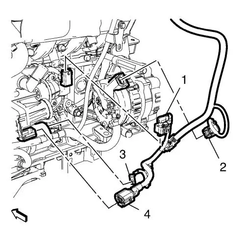
| 18. |
Unclip the retainer clip (6)
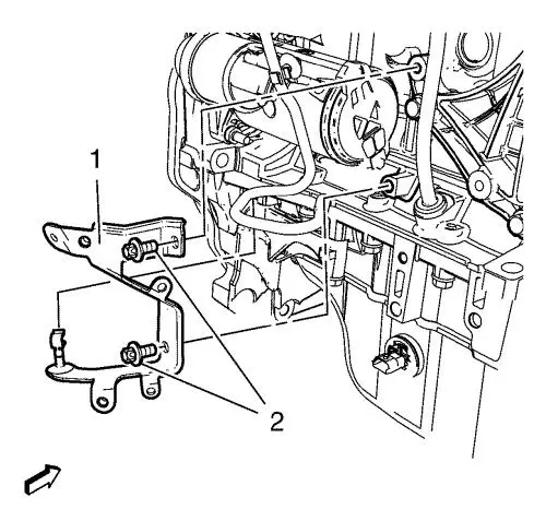
from the oil filter housing. |
| 19. |
Disconnect the turbocharger
wastegate actuator vacuum control solenoid valve wiring harness
plug (1). |
| 20. |
Unclip the retainer clip from
the turbocharger wastegate actuator vacuum control solenoid valve
bracket. |
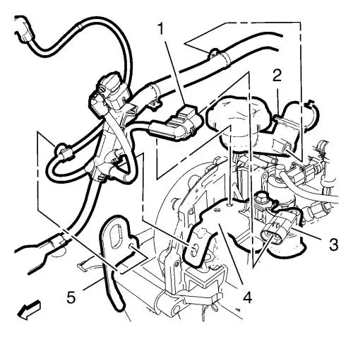
| 21. |
Disconnect the camshaft sensor
wiring harness plug (1) from the camshaft sensor (3). |
| 22. |
Unclip the 3 retainer clips
from: |
| |
• |
Engine lift bracket (5)
|
| |
• |
Engine sight shield stud
bracket (4) |
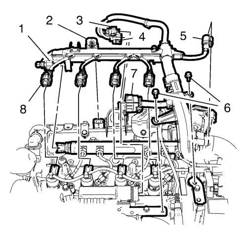
| 23. |
Disconnect the 4 fuel injector
wiring harness plugs (8). |
| 24. |
Disconnect the fuel rail
sensor wiring harness plug (1). |
| 25. |
Disconnect the manifold
absolute pressure sensor wiring harness plug (2). |
| 26. |
Disconnect the oxygen sensor
wiring harness plug (3). |
| 27. |
Disconnect the exhaust
pressure sensor wiring harness plug (4). |
| 28. |
Disconnect the throttle body
wiring harness plug (5). |
| 29. |
Remove the 2 wiring harness
bracket bolts (6). |
| 30. |
Unclip the engine control
module wiring harness from the radiator inlet hose bracket.
|
| 31. |
Disconnect the glow plug
wiring harness connector (7). |
| 32. |
Disconnect the engine coolant
temperature sensor wiring harness plug from the thermostat
housing. |
| 33. |
Disconnect the oil temperature
sensor wiring harness plug from the oil temperature sensor.
|
| 34. |
Disconnect the crankshaft
position sensor wiring harness plug from the crankshaft position
sensor. |
| 35. |
Disconnect the fuel injection
fuel pump wiring harness plug from the fuel injection fuel
pump. |
| 36. |
Disconnect the backup lamp
switch wiring harness plug from the backup lamp switch.
|
| 37. |
Unclip the wiring harness
retainer clips. |
| 41. |
Remove the upper turbocharger
wastegate actuator pipe (1). |
| 42. |
Remove the lower turbocharger
wastegate actuator pipe (4). |
| 43. |
Remove the 2 exhaust gas
recirculation valve vacuum tank bolts (2). |
| 44. |
Remove the exhaust gas
recirculation valve vacuum tank (3) from the exhaust gas
recirculation valve vacuum tank bracket (5). |
| 45. |
Unclip the turbocharger
wastegate actuator pipe from the turbocharger wastegate actuator
pipe clip. |
| 46. |
Remove the 2 exhaust gas
recirculation valve vacuum tank bracket bolts (2). |
| 47. |
Remove the exhaust gas
recirculation valve vacuum tank bracket (1). |
| 48. |
Remove the starter positive
cable nut (3). |
| 49. |
Disconnect the generator
wiring harness plug (2). |
| 50. |
Disconnect the exhaust gas
recirculation valve wiring harness plug (1). |
| 51. |
Disconnect the exhaust gas
recirculation cooler wiring harness plug (4). |
| 52. |
Unclip the wiring harness from
oil level indicator tube. |
| 53. |
Unclip the wiring harness from
the exhaust gas recirculation cooler. |
| 55. |
Remove the engine control
module wiring harness from the vehicle. |
Installation Procedure
| 1. |
Position the engine control
module wiring harness to the vehicle. |
| 3. |
Install the starter positive
cable nut (3) and tighten. |
| 4. |
Clip in the wiring harness to
the exhaust gas recirculation cooler. |
| 5. |
Clip in the wiring harness to
the oil level indicator tube. |
| 6. |
Connect the exhaust gas
recirculation cooler wiring harness plug (4). |
| 7. |
Connect the exhaust gas
recirculation valve wiring harness plug (1). |
| 8. |
Connect the generator wiring
harness plug (2). |
| 9. |
Install the exhaust gas
recirculation valve vacuum tank bracket (1). |
| 10. |
Install the 2 exhaust gas
recirculation valve vacuum tank bracket bolts (2) and tighten to
22 N·m (16 lb ft) . |
| 11. |
Install the exhaust gas
recirculation valve vacuum tank (3) to the exhaust gas
recirculation valve vacuum tank bracket (5). |
| 12. |
Install the 2 exhaust gas
recirculation valve vacuum tank bolts (2) and tighten to 8
N·m (71 lb in) . |
| 16. |
Clip the wiring harness
retainer clips. |
| 17. |
Connect the backup lamp switch
wiring harness plug to the backup lamp switch. |
| 18. |
Connect the fuel injection
fuel pump wiring harness plug to the fuel injection fuel
pump. |
| 19. |
Connect the crankshaft
position sensor wiring harness plug to the crankshaft position
sensor. |
| 20. |
Connect the oil temperature
sensor wiring harness plug to the oil temperature sensor.
|
| 21. |
Connect the engine coolant
temperature sensor wiring harness plug to the thermostat
housing. |
| 22. |
Connect the glow plug wiring
harness connector (7). |
| 23. |
Clip in the engine control
module wiring harness to the radiator inlet hose bracket.
|
| 24. |
Install the 2 wiring harness
bracket bolts (6) and tighten to 9 N·m (80 lb
in) . |
| 25. |
Connect the throttle body
wiring harness plug (5). |
| 26. |
Connect the exhaust pressure
sensor wiring harness plug (4). |
| 27. |
Connect the oxygen sensor
wiring harness plug (3). |
| 28. |
Connect the manifold absolute
pressure sensor wiring harness plug (2). |
| 29. |
Connect the fuel rail sensor
wiring harness plug (1). |
| 30. |
Connect the 4 fuel injector
wiring harness plugs (8). |
| 31. |
Connect the camshaft sensor
wiring harness plug (1) to the camshaft sensor (3). |
| 32. |
Clip in the 3 retainer clips
to: |
| |
• |
Engine lift bracket (5)
|
| |
• |
Engine sight shield stud
bracket (4) |
| 33. |
Clip in the retainer clip to
the turbocharger wastegate actuator vacuum control solenoid valve
bracket. |
| 34. |
Connect the turbocharger
wastegate actuator vacuum control solenoid valve wiring harness
plug (1). |
| 35. |
Clip in the retainer clip (6)
to the oil filter housing. |
| 36. |
Connect the turbocharger
wastegate sensor wiring harness plug (2). |
| 37. |
Clip in the retainer clip (4)
to the exhaust temperature sensor wiring harness bracket.
|
| 38. |
Connect the exhaust
temperature sensor wiring harness plug (5). |
| 39. |
Connect the air conditioning
compressor wiring harness plug (3). |
| 40. |
Clip in the oxygen sensor plug
to the exhaust pressure sensor bracket and engine control module
wiring harness. |
| 41. |
Connect the positive crankcase
ventilation pipe connector wiring harness plug. |
| 42. |
Connect the positive crankcase
ventilation pipe connector (3) to the positive crankcase
ventilation oil separator. |
| 43. |
Connect the 2 wiring harness
plugs (1, 2). |
| 44. |
Install the 3 wiring harness
(2). |
| 45. |
Install the 3 ground nuts (1)
and tighten to 9 N·m (80 lb in) .
|
| 46. |
Clip in the 3 wiring harness
plugs (3). |
| 47. |
Connect the wiring harness
plug to the front compartment fuse block. |
| 49. |
Install the windshield washer
solvent container filler tube (1). |
| 50. |
Install the 2 electronic
steering pump ground cables (2). |
| 51. |
Install the electronic
steering pump ground cable nut (1) and tighten to 9
N·m (80 lb in) . |
|
