Engine Replacement - 1.6L LLU - 6T45
Special Tools
| • |
CH-49289 Centring Frame |
| • |
CH-49290 Engine Support Tool |
For equivalent regional tools, refer to
Special Tools .
Removal Procedure
Warning: Refer to
Petrol/Petrol Vapours Warning in the
Preface section.
- Remove the lower intermediate steering shaft bolt.
Refer to
Intermediate Steering Shaft Replacement .
- Open the bonnet.
- Recover the refrigerant. Refer to
Refrigerant Recovery and Recharging .
- Remove the battery tray. Refer to
Battery Tray Replacement .
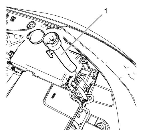
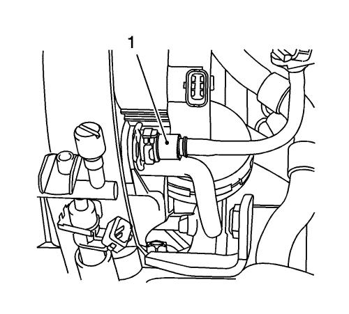
- Remove the windscreen washer solvent container filler
tube (1).
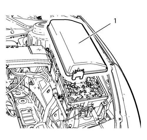
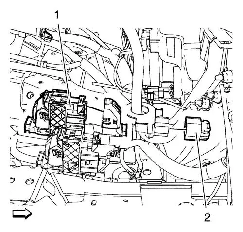
- Remove the front compartment fuse block
cover (1).
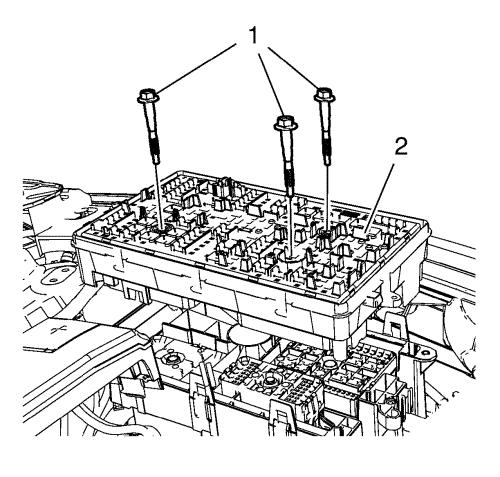
- Remove the 3 front compartment fuse block
bolts (1).
- Remove the front compartment fuse block (2).
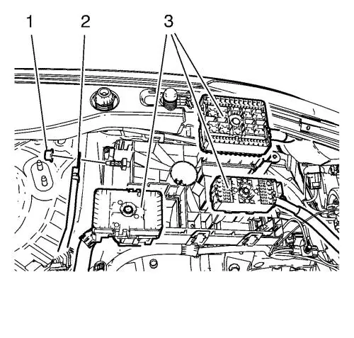
- Unclip the 3 wiring harness plugs (3).
- Disconnect the wiring harness plug from the front
compartment fuse block.
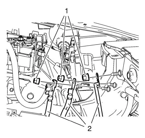
- Remove the 3 ground nuts (1) and put the
3 wiring harnesses (2) aside.
- Disconnect the 2 wiring harness
plugs (1, 2).
- Remove the air cleaner outlet duct. Refer to
Air Cleaner Outlet Front Duct Replacement .
- Remove the front bumper fascia. Refer to
Front Bumper Fascia Replacement .
- Remove the front tyre and wheel assembly. Refer to
Tyre and Wheel Removal and Installation .
- Drain the cooling system. Refer to
Cooling System Draining and Filling .
- Disconnect the coolant fill sensor plug.
- Unclip the radiator surge tank.
- Put the radiator surge tank aside.
- Remove the range selector lever cable from the
automatic transmission. Refer to
Range Selector Lever Cable Replacement .
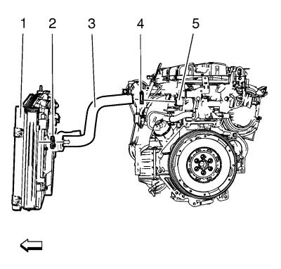
- Remove the heater inlet and outlet hose from the
bulkhead. Refer to
Heater Inlet and Outlet Hose Replacement .
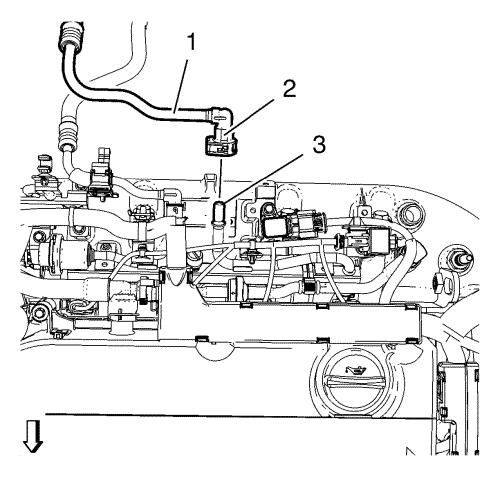
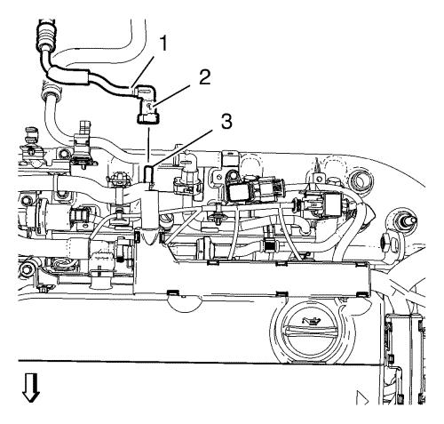
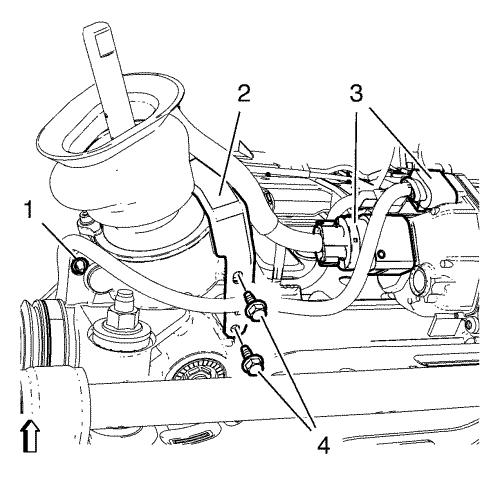
- Disconnect the booster vacuum pipe (1) from the
inlet manifold.
- Disconnect reverse lamp switch wiring harness
electrical connector.
- Place collecting basin underneath.
Warning: Petrol or petrol vapours
are highly flammable. A fire could occur if an ignition source is
present. Never drain or store petrol or diesel fuel in an open
container, due to the possibility of fire or explosion. Have a dry
chemical (Class B) fire extinguisher nearby.
- Relieve the fuel pressure. Refer to
Fuel Pressure Relief .
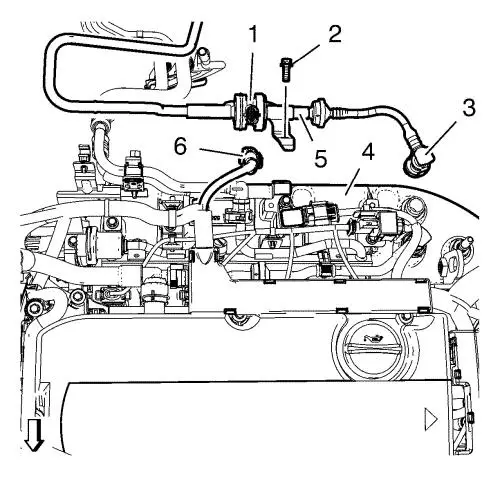
- Remove the evaporative emission vent pipe (5)
from the intake manifold (4).
| • |
Disconnect the wiring harness (6) from the
evaporative emission vent purge valve (1). |
| • |
Close the vents with the EN-6015
plugs. |
| • |
Remove the evaporative emission vent pipe retainer
bolt (2). |
| • |
Unclip the evaporative emission vent pipe from the
engine wiring harness bracket. |
- Disconnect the fuel filler pipe (1) from the fuel
rail (3).
| • |
Release the quick connector (2). |
| • |
Close the vents with the EN-6015
plugs. |
| • |
Unclip the fuel filler pipe from the engine wiring
harness bracket. |
- Disconnect the fuel return pipe (1) from the fuel
rail (3).
| • |
Release the quick connector (2). |
| • |
Close the vents with the EN-6015
plugs. |
| • |
Unclip the fuel return pipe from the engine wiring
harness bracket. |
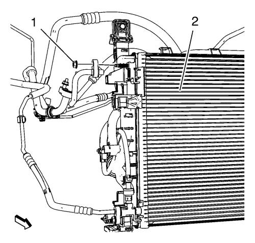
- Remove the A/C compressor and condenser hose
nut (1) from the A/C condenser (2).
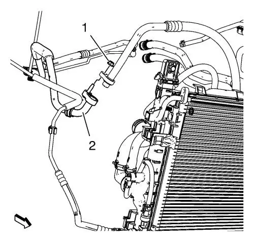
- Remove the A/C compressor and condenser hose
nut (1) from the refrigerant hose (2).
- Remove the air conditioning evaporator hose assembly
nut from the air conditioning condenser.
- Unclip the radiator outlet hose from the
radiator.
- Raise and support the vehicle. Refer to
Lifting and Jacking the Vehicle .
- Remove the front compartment splash shield. Refer to
Front Compartment Splash Shield Replacement .
- Remove the upper stabiliser shaft link from the
absorber on both sides. Refer to
Stabilizer Shaft Link Replacement .
- Remove steering linkage outer track rod from the
steering knuckle on both sides. Refer to
Steering Linkage Outer Track rod Replacement .
- Remove the front lower control arm from the steering
knuckle. Refer to
Lower Control Arm Replacement .
- Remove the front wheel shafts from the wheel hubs.
Refer to
Front Wheel Drive Shaft Replacement - Right Side and
Front Wheel Drive Shaft Replacement - Left Side .
- Disconnect the wheel speed sensors on both sides.
- Remove the wheel speed sensor wiring harness retainers
from the frame.
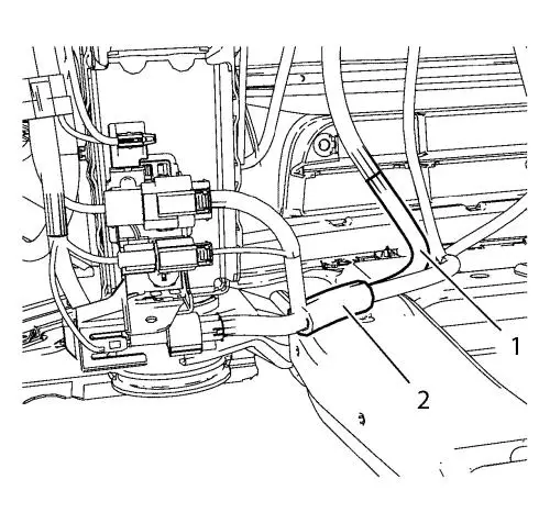
- Unclip the 2 engine coolant fan wiring
harnesses (1, 2) from the frame.
- Remove the exhaust front pipe. Refer to
Exhaust Front Pipe Replacement .
- Install the CH-49290 engine support tool ,
for the assembly use attached installation manual.
- Remove the engine mount. Refer to
Engine Mount Replacement .
- Remove the transmission mount. Refer to
Transmission Mount Replacement - Left Side .
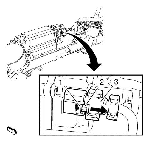
- Disconnect the electronic power steering (EPS)
electrical connector (3).
| 46.1. |
Release the lock (2) by moving in direction
of arrow, use suitable screwdriver. |
| 46.2. |
Push down the latch (1) and pull off the
electrical connector, use suitable screwdriver. |
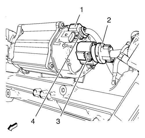
- Disconnect the electronic power steering (EPS)
electrical connector (2).
| 47.1. |
Gently lift latch (3), using angled
screwdriver. |
| 47.2. |
Pull off electrical connector (2). |
- Disconnect the electronic power steering (EPS)
electrical connector (1).
| 48.1. |
Gently lift latch (4), using angled
screwdriver. |
| 48.2. |
Pull off electrical connector (1). |
- Assemble the CH-49289 centring frame, for the
assembly use attached installation manual.
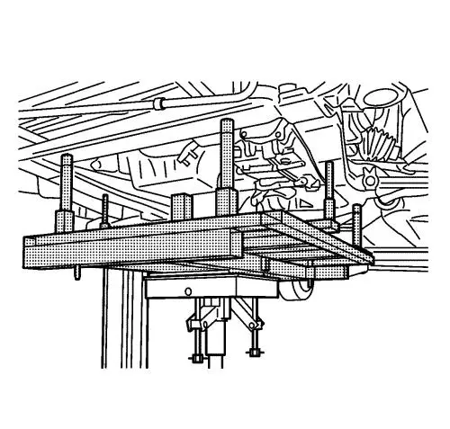
- Raise the CH-904 frame and CH-49289
centring frame with the hydraulic jack until it contacts the
frame.
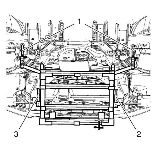
Note: Positioning
pins (2, 3) of CH-49289 centring frame MUST
insert into holes of drivetrain frame.
- Check if wheel alignment is required.
| • |
Move out position pins (1) and try to insert
into underbody holes. |
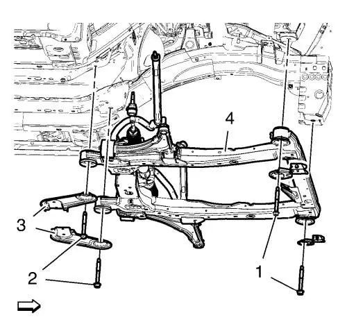
- Remove the frame front bolts (1).
- Remove the frame rear bolts (2).
- Remove the frame reinforcements (3).
- Lower suspension frame (4) carefully with the
engine transmission unit off the vehicle with hydraulic jack about
7 cm (2.75 in) .
- Remove the 2 wiring harness bracket
bolts (4).
- Remove the bracket (2) from the vehicle.
- Remove the suspension frame carefully with the engine
transmission unit from the vehicle with hydraulic jack.
- Remove the right wheel drive shaft from the
transmission. Refer to
Front Wheel Drive Shaft Seal Replacement - Right Side .
- Remove the left wheel drive shaft from the
transmission. Refer to
Front Wheel Drive Shaft Seal Replacement - Left Side .
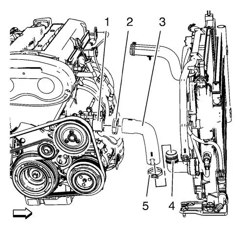
- Loosen the radiator outlet hose clamp (2).
- Remove the radiator outlet hose (3) from the
water pump (1).
- Loosen the radiator inlet hose clamp (4).
- Remove the radiator inlet hose (3) from the
engine coolant thermostat (5).
- Install suitable cable at the 3 engine lift
brackets.
- Install a suitable engine lifting device to the
cable.
- Extend the engine lifting device until the steel cable
are slightly tensioned.
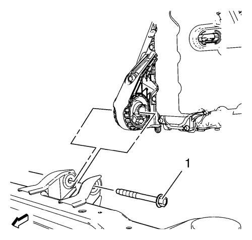
- Remove the front transmission mount through
bolt (1).
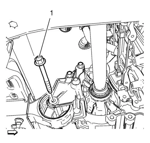
- Remove the rear transmission bracket mount to mount
through bolt (1).
- Lower and remove the frame.
- Put the engine transmission unit down on a wooden
pallet.
- Loosen the 8 transmission bolts and remove
6 of them. Refer to
Transmission Replacement .
Note: A second technician is
required.
- Remove the last 2 transmission bolts and the
transmission.
- Install the engine to the EN-49271 engine
stand .
- Transfer parts as needed.
Installation Procedure
- Remove the engine from the EN-49271 engine
stand .
- Put the engine down on a wooden pallet.
Note: A second technician is
required.
- Install the transmission and 2 transmission
bolts.
- Install the 6 transmission bolts.
Caution: Refer to
Fastener Caution in the Preface
section.
- Tighten the 8 transmission bolts. Refer to
Transmission Replacement .
- Install suitable cable at the 3 engine lift
brackets. Install a suitable engine lifting device to the cable.
Raise the engine transmission unit and extend the engine lifting
device until the steel cables are slightly tensioned.
- Raise the CH-904 frame and CH-49289
centring frame with the hydraulic jack until it contacts the
frame.
- Place the engine transmission unit into the front
frame.
- Install the rear transmission bracket mount to mount
through bolt (1) and tighten to
100 N·m (74 lb ft)
.
- Install the front transmission mount through
bolt (1) and tighten to
58 N·m (43 lb ft)
.
- Remove the cable from the 3 engine lift
brackets.
- Install the radiator inlet hose (3) to the engine
coolant thermostat (5).
- Install the radiator inlet hose clamp (4).
- Install the radiator outlet hose (3) to the water
pump (1).
- Install the radiator outlet hose clamp (2).
- Install the right wheel drive shaft to the
transmission. Refer to
Front Wheel Drive Shaft Seal Replacement - Right Side .
- Install the left wheel drive shaft to the
transmission. Refer to
Front Wheel Drive Shaft Seal Replacement - Left Side .
Note: Positioning pins (1)
of CH-49289 centring frame MUST be extended in order to
guide into underbody holes.
- Move the frame with the engine transmission unit to
the vehicle upwards, until wiring harness starter can be
fixed.
- Install and tighten the 2 wiring harness bracket
bolts (4) to
9 N·m (80 lb in) .
- Install the frame (4).
- Install the frame reinforcements.
- Install the frame rear bolts (2). Handtighten
ONLY.
- Install the frame front bolts . Handtighten
ONLY.
- Tighten the rear frame bolts (2) and tighten
to
160 N·m (118 lb ft)
.
- Tighten the front frame bolts (1) and tighten
to
160 N·m (118 lb ft)
.
- Lower the CH-49289 centring frame with the
hydraulic jack until it is removable.
- Disassemble the CH-49289 centring frame , for
the assembly use attached installation manual.
- Install the engine mount. Refer to
Engine Mount Replacement .
- Install the transmission mount. Refer to
Transmission Mount Replacement - Left Side .
- Remove the CH-49290 engine support tool , for
the disassembly use attached installation manual.
- Connect electrical connector (1) until you hear
it click.
- Connect electrical connector (2) until you hear
it click.
- Connect electrical connector (3) until you hear
it click.
- Push back lock (2) in opposite direction of arrow
until you hear it click.
- Install the exhaust front pipe. Refer to
Exhaust Front Pipe Replacement .
- Clip the 2 engine coolant fan wiring
harnesses (1, 2) into the frame.
- Install the wheel speed sensor wiring harness
retainers from the frame.
- Connect the wheel speed sensor on both sides.
- Install the front wheel shafts to the wheel hubs.
Refer to
Front Wheel Drive Shaft Replacement - Right Side .
- Install the front lower control arm to the steering
knuckle. Refer to
Lower Control Arm Replacement .
- Install the steering linkage outer track rod to the
steering knuckle on both sides. Refer to
Steering Linkage Outer Track rod Replacement .
- Install the upper stabiliser shaft link to the
absorber on both sides. Refer to
Stabilizer Shaft Link Replacement .
- Install the front compartment splash shield. Refer to
Front Compartment Splash Shield Replacement .
- Check the transmission fluid level. Refer to
Transmission Fluid Level Inspection .
- Lower the vehicle.
- Clip the radiator outlet hose into the radiator.
Note: Use a NEW O-ring seal.
Refer to
Air Conditioning O-Ring Seal Replacement .
- Install the air conditioning evaporator hose assembly
nut to the air conditioning condenser and tighten to
19 N·m (14 lb ft)
.
Note: Use a NEW O-ring seal.
Refer to
Air Conditioning O-Ring Seal Replacement .
- Install the A/C compressor and condenser hose
nut (1) to the A/C condenser (2). Tighten the nut to
19 N·m (14 lb ft)
.
Note: Use a NEW O-ring seal.
Refer to
Air Conditioning O-Ring Seal Replacement .
- Install the A/C compressor and condenser hose
nut (1) to the refrigerant hose (2). Tighten the nut to
19 N·m (14 lb ft)
.
- Connect the fuel return pipe (1) to the fuel
rail (3).
| • |
Remove the EN-6015 plugs. |
| • |
Clip in the fuel return pipe to the engine wiring
harness bracket. |
- Connect the fuel filler pipe (1) to the fuel
rail (3).
| • |
Remove the EN-6015 plugs. |
| • |
Install the quick connector (2). |
| • |
Clip in the fuel filler pipe to the engine wiring
harness bracket. |
- Install the evaporative emission vent pipe (5) to
the intake manifold (4).
| • |
Connect the wiring harness (6) to the
evaporative emission vent purge valve (1). |
| • |
Remove the EN-6015 plugs. |
| • |
Install the evaporative emission vent pipe
retainer bolt (2) and tighten to
8 N·m (71 lb in) . |
| • |
Clip in the evaporative emission vent pipe to the
engine wiring harness bracket. |
- Connect reverse lamp switch wiring harness electrical
connector.
- Connect the booster vacuum pipe (1) to the inlet
manifold.
- Install the heater inlet and outlet hose from the
bulkhead. Refer to
Heater Inlet and Outlet Hose Replacement .
- Install the range selector lever cable to the
automatic transmission. Refer to
Range Selector Lever Cable Replacement .
- Clip in the radiator surge tank.
- Connect the radiator surge tank wiring harness.
- Fill the cooling system. Refer to
Cooling System Draining and Filling .
- Install the front tyre and wheel assembly. Refer to
Tyre and Wheel Removal and Installation .
- Install the front bumper fascia. Refer to
Front Bumper Fascia Replacement .
- Install the air cleaner outlet duct. Refer to
Air Cleaner Outlet Front Duct Replacement .
- Connect the 2 wiring harness
plugs (1, 2).
- Install the 3 wiring harnesses (2).
- Install the 3 ground nuts (1) and tighten
to
9 N·m (80 lb in) .
- Clip in the 3 wiring harness plugs (3).
- Connect the wiring harness plug to the front
compartment fuse block.
- Install the front compartment fuse
block (2).
- Install the 3 front compartment fuse block
bolts (1) and tighten to
22 N·m (16 lb ft)
.
- Install the front compartment fuse block
cover (1).
- Install the windscreen washer solvent container filler
tube (1).
- Install the battery tray. Refer to
Battery Tray Replacement .
- Evacuate and charge the refrigerant system. Refer to
Refrigerant Recovery and Recharging .
- Check the oil level and fill engine oil, if
necessary.
- Close the bonnet.
- Install the lower intermediate steering shaft bolt.
Refer to
Intermediate Steering Shaft Replacement .
|
