Engine Replacement (1.7L Diesel LPL and LPV)
Special Tools
| • |
CH-49289
Centering Adapter |
| • |
CH-49290
Mounting Engine/Transmission |
For equivalent regional tools, refer to
Special Tools .
Removal Procedure
Warning: Refer to
Gasoline/Gasoline Vapors Warning .
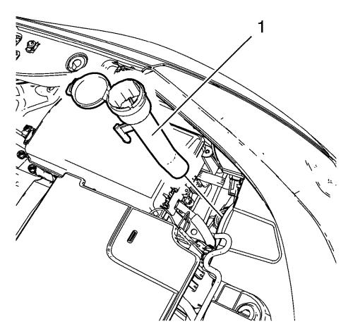
| 6. |
Remove the windshield washer
solvent container filler tube (1). |
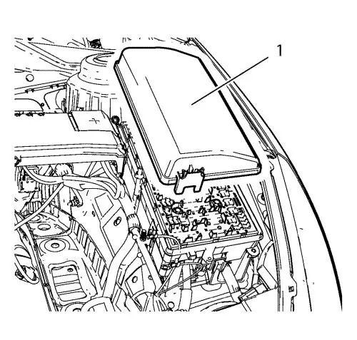
| 7. |
Remove the front compartment
fuse block cover (1). |
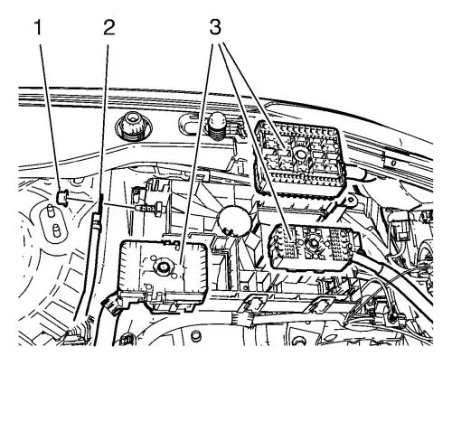
| 9. |
Unclip the 3 wiring harness
plugs (3). |
| 10. |
Disconnect the wiring harness
plug from the front compartment fuse block. |
| 11. |
Remove the 3 ground nuts (1)
and put the 3 wiring harnesses (2) aside. |
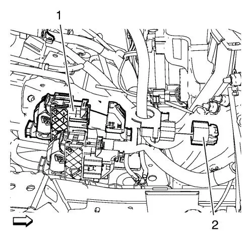
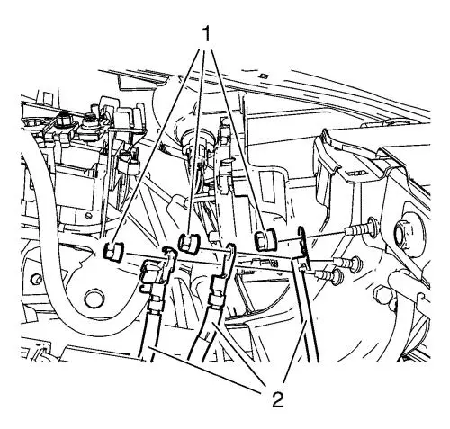
| 12. |
Disconnect the 2 wiring
harness plugs (1, 2). |
| 20. |
Disconnect the booster vacuum
pipe from the vacuum pump. |
| 21. |
Disconnect the backup lamp
switch wiring harness electrical connector. |
| 22. |
Place collecting basin
underneath the vehicle. |
| 24. |
Place a collecting basin
underneath the vehicle. |
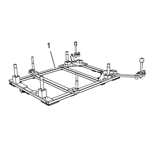
|
Warning:
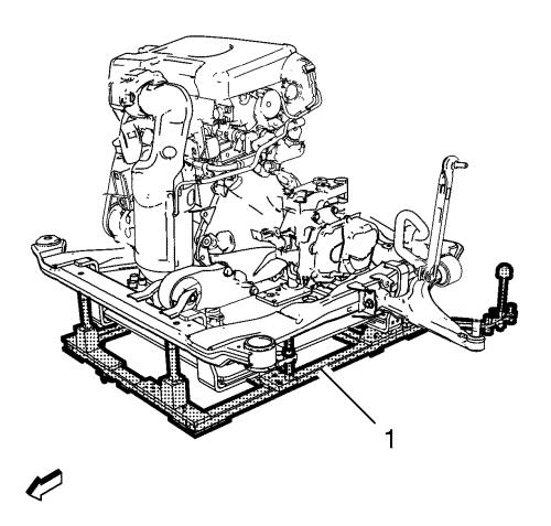
Always wear safety goggles when working with fuel
in order to protect the eyes from fuel splash. |
| 26. |
Close all connections with
EN-6015 plugs . |
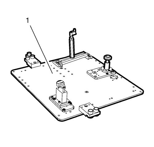
| 27. |
Close the connection from fuel
injection pump by using EN-6368 plugs .
|
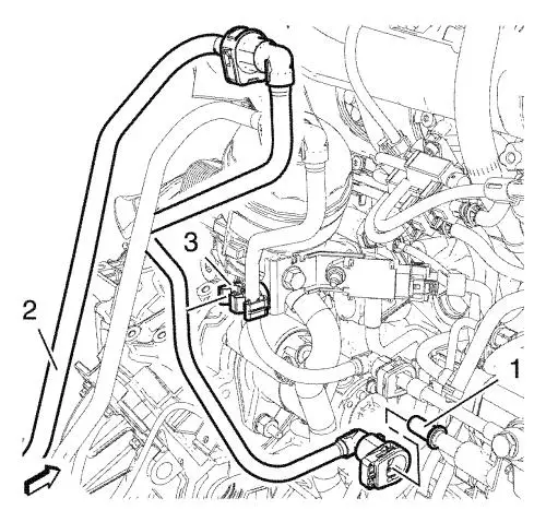
| 28. |
Remove the fuel feed pipe (2)
from the retainer clip (3). |
| 30. |
Close all connections with
EN-6015 plugs . |
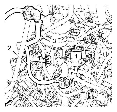
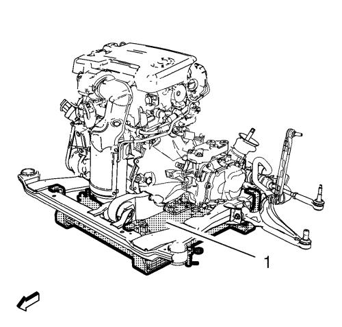
| 31. |
Remove the fuel return pipe
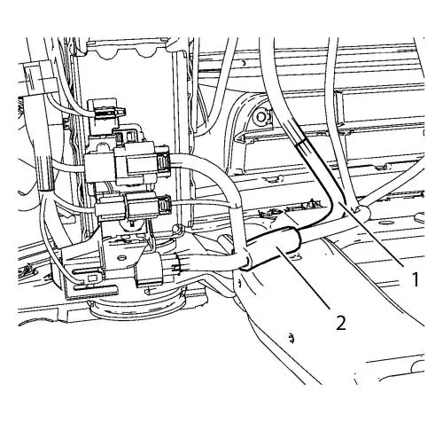
(2) from the retainer clip (3). |
| 39. |
Disconnect the wheel speed
sensors on both sides. |
| 40. |
Remove the wheel speed sensor
wiring harness retainers from the frame. |
| 41. |
Unclip the 2 engine coolant
fan wiring harnesses (1, 2) from the frame. |
|
Note: The SPX
installation manual is supplied with the special tool and is also
available online from SPX directly. Go to
www.spxtools-shop.com.
|
| 43. |
Assemble the CH-49290
engine support tool (1) according to the details provided in
the SPX installation manual. |
| 44. |
Support the CH-904
base frame on a jack. |
| 45. |
Support the CH-49290
engine support tool on the CH-904 base frame
. |
| 46. |
Install the CH-49290
engine support tool (1) according to the details provided in
the SPX installation manual. |
| 49. |
Detach the 3 wiring harness
plugs from the electronic power steering (EPS). |
|
Note: The SPX
installation manual is supplied with the special tool and is also
available online from SPX directly. Go to
www.spxtools-shop.com.
|
| 50. |
Assemble the CH-49289
centering frame (1) according to the details provided in the
SPX installation manual. |
| 51. |
Support the CH-904
base frame on a jack. |
| 52. |
Support the CH-49289
centring frame on the CH-904 base frame
. |
|
Note: The SPX
installation manual is supplied with the special tool and is also
available online from SPX directly. Go to
www.spxtools-shop.com.
|
| 53. |
Install the CH-49289
centering frame (1) according to the details provided in the
SPX installation manual. |
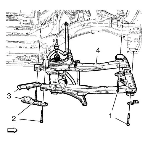
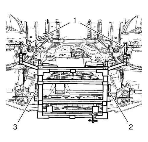
| 54. |
Remove the frame front bolts
(1). |
| 55. |
Remove the frame rear bolts
(2). |
| 56. |
Remove the frame
reinforcements (3). |
| 57. |
Lower the suspension frame (4)
carefully with the engine transmission unit off the vehicle with
hydraulic jack about 7 cm (2.75 in) . |
| 58. |
Remove the 2 wiring harness
starter bracket bolts. |
| 59. |
Remove the wiring harness
starter bracket from the electronic power steering (EPS).
|
| 60. |
Remove the suspension frame
carefully with the engine transmission unit from the vehicle with
hydraulic jack. |
|
Note: Place a
collecting basin underneath.
|
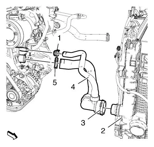
| 62. |
Remove the radiator outlet
hose clamps (1, 5). |
| 63. |
Place a collecting basin
underneath the vehicle. |
| 64. |
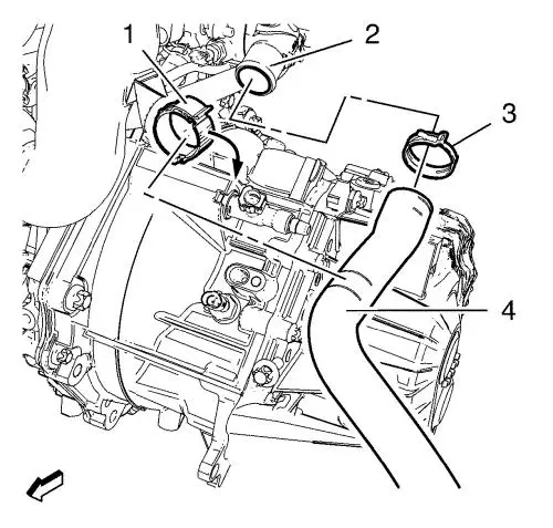
Unlatch the radiator inlet
hose bracket clip (1). |
| 65. |
Remove the radiator inlet hose
clamp (3). |
| 66. |
Remove the radiator inlet hose
(4) from the water outlet (2). |
| 67. |
Install suitable cable to the
3 engine lift brackets. |
| 68. |
Install a suitable engine
lifting device to the cable. |
| 69. |
Extend the engine lifting
device until the steel cable are slightly tensioned. |
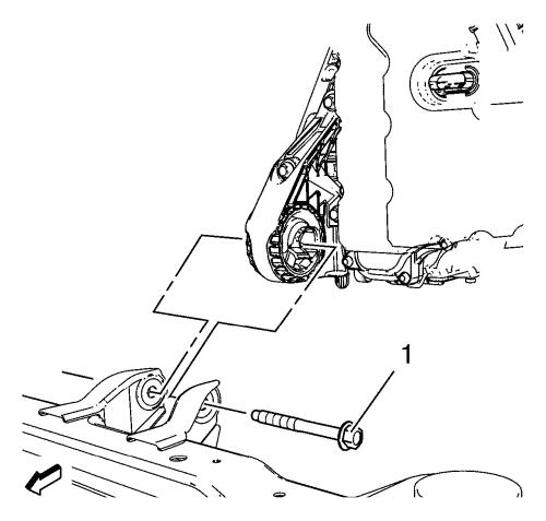
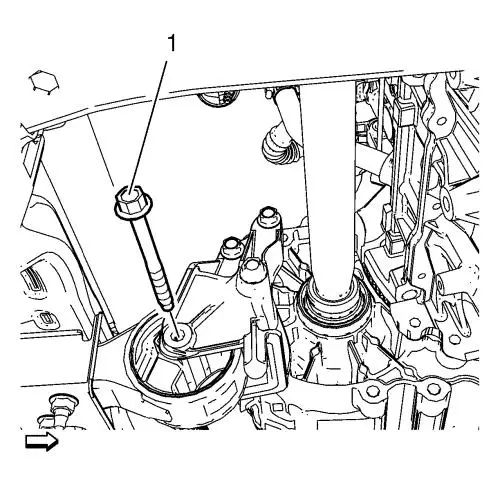
| 70. |
Remove the front transmission
mount through bolt (1). |
| 71. |
Remove the rear transmission
bracket mount to mount through bolt (1). |
| 72. |
Lower and remove the
frame. |
| 73. |
Put the engine transmission
unit down on a wooden pallet. |
|
Note: A second
technician is required.
|
| 75. |
Remove the last 2 transmission
bolts and the transmission. |
| 76. |
Install the engine to a
suitable engine stand. |
| 77. |
Transfer parts as
needed. |
Installation Procedure
| 1. |
Remove the engine from the
engine stand. |
| 2. |
Put the engine down on a
wooden pallet. |
|
Note: A second
technician is required.
|
| 3. |
Install the transmission and 2
transmission bolts. |
| 4. |
Install the 6 transmission
bolts. |
| 6. |
Install a suitable cable at
the 3 engine lift brackets. Install a suitable engine lifting
device to the cable. Raise the engine transmission unit and extend
the engine lifting device until the steel cable are slightly
tensioned. |
| 7. |
Raise the CH-904
frame and CH-49289 adapter with the
hydraulic jack until it contacts the frame. |
| 8. |
Place the engine transmission
unit into the front frame. |
| 9. |
Install the rear transmission
bracket mount to mount through bolt (1) and tighten to 100
N·m (74 lb ft) . |
| 10. |
Install the front transmission
mount through bolt (1) and tighten to 58 N·m (43 lb
ft) . |
| 11. |
Remove the cable from the 3
engine lift brackets. |
| 12. |
Install and reposition the
radiator outlet hose clamps (1), (5) to the water inlet.
|
| 13. |
Install and reposition the
radiator inlet hose (4) to water outlet (2). |
| 14. |
Reposition and tighten the
radiator inlet hose clamp (3). |
| 15. |
Latch the radiator inlet hose
bracket clip (1). |
|
Note: Positioning
pins (1) of CH-49289 adapter MUST be extended in
order to guide into underbody holes.
|
| 17. |
Move the frame (1) with the
engine transmission unit to the vehicle upwards, till the wiring
harness starter can be fixed. |
| 18. |
Install the wiring harness
starter bracket to the electronic power steering (EPS).
|
| 19. |
Install and tighten the 2
wiring harness starter bracket bolts. |
| 20. |
Install the frame (4).
|
| 21. |
Install the frame
reinforcements (3). |
| 22. |
Install the frame rear bolts
(2). Hand tighten ONLY. |
| 23. |
Install the frame front bolts
(3). Hand tighten ONLY. |
| 24. |
Tighten the rear frame bolts
(2) and tighten to 160 N·m (118 lb ft)
. |
| 25. |
Tighten the front frame bolts
(1) and tighten to 160 N·m (118 lb ft)
. |
| 26. |
Lower the CH-49289
centring frame (1) with the CH-904 base
frame and a jack. |
| 27. |
Remove the CH-49289
centring frame from the CH-904 base frame
. |
|
Note: The SPX
installation manual is supplied with the special tool and is also
available online from SPX directly. Go to
www.spxtools-shop.com.
|
| 28. |
Disassemble the
CH-49289 centering frame (1) according to the
details provided in the SPX installation manual. |
| 31. |
Lower the CH-49290
engine support tool (1) with the CH-904 base
frame and a jack. |
| 32. |
Remove the CH-49290
engine support tool from the CH-904 base
frame . |
|
Note: The SPX
installation manual is supplied with the special tool and is also
available online from SPX directly. Go to
www.spxtools-shop.com.
|
| 33. |
Disassemble the
CH-49290 engine support tool (1) according to the
details provided in the SPX installation manual. |
| 34. |
Connect the 3 wiring harness
connectors to the electronic power steering (EPS). |
| 36. |
Clip the 2 engine coolant fan
wiring harnesses (1, 2) into the frame. |
| 37. |
Install the wheel speed sensor
wiring harness retainers from the frame. |
| 38. |
Connect the wheel speed sensor
on both sides. |
| 46. |
Clip the radiator outlet hose
into the radiator. |
| 48. |
Remove the EN-6015
plugs from all connections. |
| 49. |
Remove the EN-6368
plugs from the fuel injection pump. |
| 51. |
Install the fuel feed pipe (2)
to the retainer clip (3). |
| 52. |
Install the fuel return pipe
(2) into the bracket clip (3). |
| 53. |
Remove the EN-6015
plugs from all connections. |
| 57. |
Fill the reservoir with
clutch/brake fluid up to the MAX level. |
| 58. |
Connect the backup lamp switch
wiring harness electrical connector. |
| 59. |
Connect the booster vacuum
pipe to the vacuum pump. |
| 62. |
Clip in the radiator surge
tank. |
| 63. |
Connect the radiator surge
tank wiring harness. |
| 68. |
Connect the 2 wiring harness
plugs (1, 2). |
| 69. |
Install the 3 wiring harnesses
(2). |
| 70. |
Install the 3 ground nuts (1)
and tighten to 9 N·m (80 lb in) .
|
| 71. |
Clip in the 3 wiring harness
plugs (3). |
| 72. |
Connect the wiring harness
plug to the front compartment fuse block. |
| 74. |
Install the front compartment
fuse block cover (1). |
| 75. |
Install the windshield washer
solvent container filler tube (1). |
| 78. |
Check the oil level and fill
NEW engine oil up if necessary. |
|
