Camshaft Cover Replacement (1.7L Diesel LPL and LPV)
Special Tools
EN-6368 Set of Plugs
For equivalent regional tools, refer to
Special Tools .
Removal Procedure
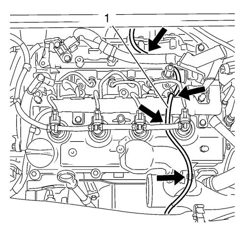
| 4. |
Detach the vacuum hose (1)
from the exhaust gas recirculation cooler. |
| 5. |
Unclip the vacuum hose from
the 4 retainer clips (arrows) and put the vacuum hose aside.
|
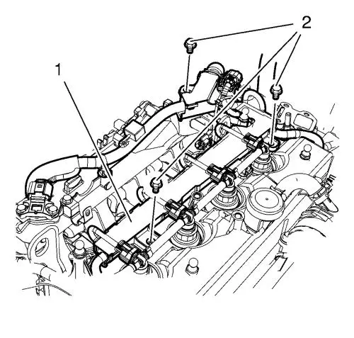
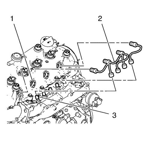
| 6. |
Remove the 3 wiring harness
bolts (2) from the wiring harness (1). |
| 7. |
Disconnect the following
engine wiring harness plugs: |
| |
• |
Coolant temperature sensor
wiring harness plug |
| |
• |
Exhaust gas recirculation
valve wiring harness plug |
| |
• |
Throttle body wiring harness
plug |
| |
• |
4 Injector wiring harness
plugs |
| |
• |
4 glow plug wiring harness
plugs |
| |
• |
Camshaft sensor wiring harness
plug |
| |
• |
Air intake temperature sensor
wiring harness plug |
| |
• |
2 solenoid valve wiring
harness plugs |
| |
• |
Engine control module wiring
harness plug |
| |
• |
Glow plug controller wiring
harness plug |
| |
• |
Wiring harness connection
plug |
| 8. |
Remove the wiring harness from
the 6 retainer clips and put the wiring harness (1) aside.
|
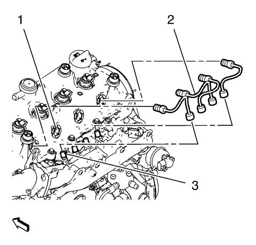
| 9. |
Loosen the 8 fuel injection
fuel feed pipe connecting nuts. |
| 10. |
Remove the 4 fuel injection
fuel feed pipes (2). |
| 11. |
Plug the fuel injector
connections (1), the fuel injection fuel feed pipes (2) and the
fuel rail (3) by using EN-6368 plugs . |
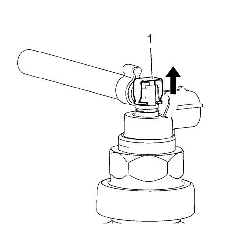
| 12. |
Disconnect the 4 fuel injector
fuel return hose clips (1). |
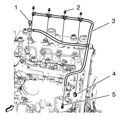
| 13. |
Disconnect the fuel return
hose clip (4). |
| 14. |
Remove the fuel return hose
hollow screw (1) and the 2 copper seal rings. |
| 15. |
Disconnect the fuel injection
fuel return hose (3) from the fuel injection pump connector (5) and
the fuel injectors. |
|
Note: Plug the fuel
injectors and the fuel injection pump in order to prevent
contamination.
|
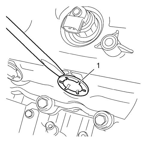
| 16. |
Remove the 4 fuel injector
seal rings (1) from the camshaft cover. |
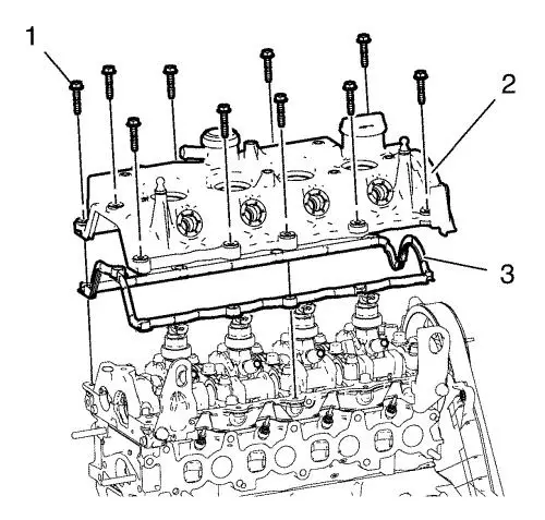
| 17. |
Remove the 10 camshaft cover
bolts (1). |
| 18. |
Remove the camshaft cover (2)
and the gasket (3). |
Installation Procedure
| 1. |
Clean the sealing
surfaces. |
| 2. |
Install a NEW camshaft cover
gasket (3). |
| 3. |
Install the camshaft cover
(2). |
| 4. |
Loosely install the 10
camshaft cover bolts (1). |
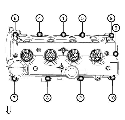
| 5. |
Tighten the 10 camshaft cover
bolts to 10 N·m (89 lb in) in sequence as
shown in the graphic. |
| 6. |
Install the 4 NEW fuel
injector seal rings. |
| 7. |
Install the fuel injection
fuel return hose (3) |
| 8. |
Connect the fuel injection
fuel return hose (3) to the fuel injection pump connector (5), to
the fuel return hose clip (4) and the fuel injectors. |
| 9. |
Install the fuel injector fuel
return hose hollow screw (1). Install the 2 NEW copper seal rings.
Tighten the hollow screw to 10 N·m (89 lb
in) . |
| 10. |
Remove all EN-6368
plugs from the fuel rail (3), fuel injectors (1) and fuel
injection fuel feed pipes (2). |
|
Note: Hand tighten
the fuel injection nuts before tighten the final torque.
|
| 11. |
Install the 4 fuel injection
fuel feed pipes (2). |
| 12. |
Tighten the 2 fuel injection
fuel rail bolts to 25 N·m (18 lb ft)
. |
|
Note: Tighten union
nuts first at injectors, then at pressure chamber.
|
| 13. |
Tighten the 8 fuel injection
fuel feed pipe connecting nuts to 25 N·m (18 lb
ft) . |
| 14. |
Connect the following engine
wiring harness plugs: |
| |
• |
Coolant temperature sensor
wiring harness plug |
| |
• |
Exhaust gas recirculation
valve wiring harness plug |
| |
• |
Throttle body wiring harness
plug |
| |
• |
4 Injector wiring harness
plugs |
| |
• |
4 glow plug wiring harness
plugs |
| |
• |
Camshaft sensor wiring harness
plug |
| |
• |
Air intake temperature sensor
wiring harness plug |
| |
• |
2 solenoid valve wiring
harness plugs |
| |
• |
Engine control module wiring
harness plug |
| |
• |
Glow plug controller wiring
harness plug |
| |
• |
Wiring harness connection
plug |
| 15. |
Clip in the wiring harness (1)
to the 6 retainer clips. |
| 16. |
Install the 3 wiring harness
bolts (2) to the wiring harness (1) and tighten to 9
N·m (80 lb in) . |
| 17. |
Clip in the vacuum hose to the
4 retainer clips (arrows). |
| 18. |
Attach the vacuum hose (1) to
the exhaust gas recirculation cooler. |
|
