Terminal Removal
Special Tools
| • |
EL-38125-580
Terminal Release Tool Kit |
| • |
EL-35616
Terminal Test Probe Kit |
For equivalent regional tools, refer to
Special Tools .
Note: All repairs near the
engine manifold, turbo engine and all exhaust pipes should follow
the High Temperature Wiring Repair procedures.
| 1. |
Find the appropriate connector
end view within the connector end view section. The connector end
view has the following information: |
| |
• |
Terminal/terminated lead part
numbers |
|
Note: Not using the
proper test kit probe may cause damage to the terminal(s) that are
probed.
|
| 2. |
Determine if a terminal is
damaged. |
| |
• |
Locate the diagnostic probe
tool from the connector end view. The connector end view describes
the color and part number to help the technician find and use the
correct tool. |
| |
• |
Connect the probe tool to the
Digital Multimeter. |
| 3. |
Disconnect the connector body
to perform the repair. |
| 4. |
Use the following procedure to
remove the terminal from the connector body. |
|
Note: Several
procedures for specific connector bodies are called out in the
Wiring Repairs section.
|
| |
• |
The terminal position
assurance (TPA) and connector position assurance (CPA) should be
removed before releasing the terminal for the connector
body. |
| |
• |
Look at the connector end view
to locate the cavity of the damaged terminal and find the proper
terminal release tool from the terminal release tool kit.
|
|
Note: Using the incorrect
terminal release tool can damage the connector body.
|
|
Note: Some terminals have a
lever that must be disengaged before the terminal can be
released.
|
| |
|
|
| |
• |
Insert the terminal release
tool into the cavity. |
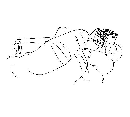
| 5. |
Gently pull the wire out of
the back of the connector. |
| 7. |
Insert the repaired terminal
back into the cavity. Repeat the diagnostic procedure to verify the
repair and reconnect the connector bodies. |
|
