Delphi Connectors (Micro-Pack 100W)
Special Tools
| • |
EL-38125-580
Terminal Release Tool Kit |
| • |
J-38125-12A
Terminal Release Tool |
For equivalent regional tools, refer to
Special Tools .
Terminal Removal Procedure
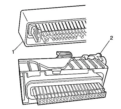
There are 2 styles of Micro-Pack 100W connectors. These
connectors are very similar but use different terminals and have
some minor physical differences also.
The first connector design of the Micro-Pack 100W (1) has
a white connector interface that holds the terminals. The second
design of the Micro-Pack 100W (2) has a gray interface to
hold the terminals. Also, the first design has terminal cavities
that are further apart (3 mm centerline) and offset from the
other row of terminal cavities in the connector. The second design
has terminals cavities that are closer together (2.54 mm
centerline) and aligned vertically. One other way to identify the
second design is the thin strip of material that runs along the
outside of the cavities.
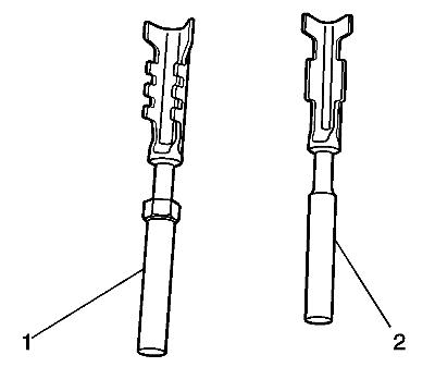
Note: There are
2 styles of Micro-Pack 100W terminals which are very
similar. Ensure that you have the correct terminal before crimping
the new terminal to the wire. The first design connector uses the
longer terminal (1) that has a raised area in front of the
recess in the terminal. The second design connector uses the
shorter terminal without the raised area.
Follow the steps below in order to remove terminals from
Micro-Pack 100W connectors. Some Micro-Pack 100W connector
disassembly procedures will vary. Use this procedure as a
guide.
| 1. |
Disconnect the connector from
the component. |
| 2. |
Locate the nose piece locking
tabs that are positioned on the side of the connector nose piece.
The connector nose piece acts as a terminal positive assurance
(TPA) and may be referred to as such. |
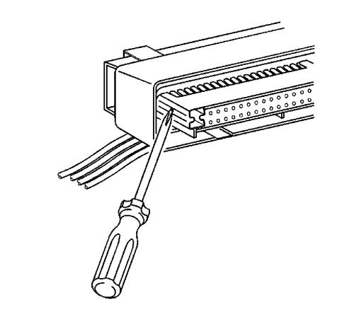
| 3. |
Use a small flat-blade tool to
push in one of the locking tabs while gently pulling on the same
side of the nose piece. |
| 4. |
Repeat the procedure for the
other locking tab and remove the nose piece. |
| 5. |
Remove the wire dress cover.
The following is a general procedure for wire dress cover removal.
Use this procedure as a guide, some dress cover removal procedures
may vary. |
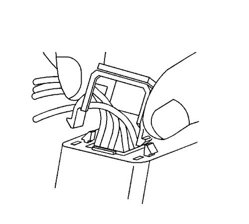
| 6. |
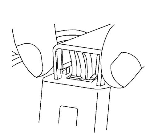
Use fingers to squeeze the
2 locking legs of the cover. |
| 7. |
Apply pressure and gently rock
the cover until one locking leg is unseated. |
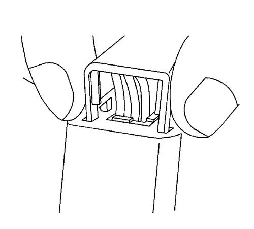
| 8. |
Continue to apply pressure and
rock the cover until the second locking leg is unseated. Repeat
procedure for the other side of the dress cover and remove the
cover. |
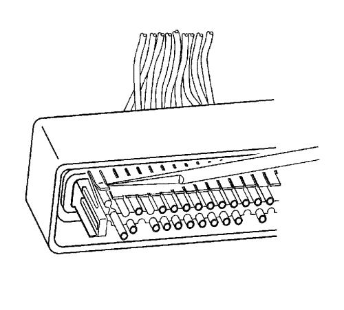
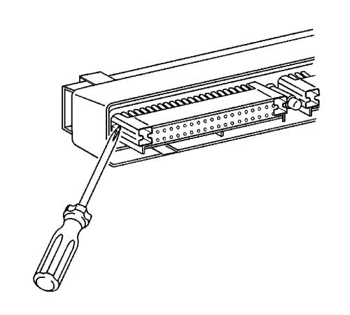
| 9. |
Use J-38125-12A to gently lift
the terminal retaining tab while gently pulling the wire out of the
back of the connector. Always remember never use force when pulling
a terminal out of a connector. |
| 10. |
If the terminal is severely
bent or damaged, it may be possible on some connectors to push the
wire out of the front of the connector instead of pulling it
through. This will prevent damage to the internal seals of the
connector. Once the terminal is pushed out of the connector, cut
the wire as close to the terminal as possible and pull the wire
through the connector. |
| 12. |
Insert the repaired terminal
back into the cavity. Repeat the diagnostic procedure to verify the
repair and reconnect the connector bodies. |
Terminal Insertion Procedure
After the terminal is crimped to the wire perform the following
procedure in order to replace Micro-Pack 100 terminals.
| 1. |
Slide the new terminal into
the correct cavity at the back of the connector. |
| 2. |
Push the terminal into the
connector until it locks into place. The new terminal should be
even with the other terminals. Ensure that the terminal is locked
in place by gently pulling on the wire. |
| 3. |
To assemble the connector,
reverse the Terminal Removal Procedure. |
|