vauxhall Workshop Repair Guides

Vauxhall Workshop Service and Repair Manuals

Vehicle Zoning Strategy - Passenger Car > < Master Electrical Schematic Icons

Electrical Schematic Symbols

Table 1: Voltage Indicators
Table 2: General Icons
Table 3: Switch Position Icons
Table 4: Module Circuit Function Icons
Table 5: Harness Components
Table 6: Component Parts
Table 7: Switches and Relays
Table 8: Devices and Sensors

Voltage Indicators


Symbol


Description


1988677


Battery Voltage


1988679


Ignition Switch– Off Position


1988682


Ignition Switch– Accessory Position


1988686


Ignition Switch– Run Position


1988691


Ignition Switch– Start Position


General Icons


Symbol


Description


1990537


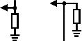
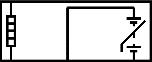
Master Component List Icon

This icon is used on the schematic to link to the Master Electrical Component List.


1990538


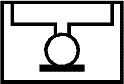
Description and Operation Icon

This icon is used on the schematic to link to the Description and Operation of that particular system.


1988674


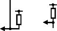
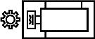
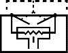
Computer Programming Icon

This icon is used on the schematic to link to Control Module References, which identifies which components need programming upon replacement.


1990541


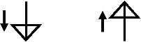
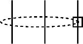
Next Schematic Page Icon

This icon is used on the schematic to navigate to the next schematic in the subsystem.


1990542


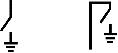
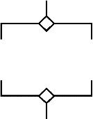
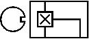
Previous Schematic Page Icon

This icon is used on the schematic to navigate to the previous schematic in the subsystem.


1988667


Supplemental Inflatable Restraint (SIR) or Supplemental Restraint System (SRS) Icon

This icon is used to alert the technician that the system contains SIR/SRS components that require certain precautions before servicing.


1988670


Information Icon

This icon is used to alert the technician that there is additional information that will aid in servicing a system.
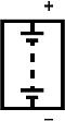


1988672


Danger Icon

This icon is intended to alert the technician that a component within the system contains labelling with the same icon.

This icon is used when a source component has potential for 60 volts DC or greater or has potential for 42 volts AC or greater.


1988673


High Voltage Icon

This icon is intended to alert the technician that a component within the system contains labelling with the same icon.

This icon is used when a component/circuit has potential for 60 volts DC or greater or has potential for 42 volts AC or greater.


1990543


Caution Icon

This icon is used to advise the technician to use caution when servicing this component.

This icon may be used when a component/circuit has a voltage range potential between 30-60 volts DC or 15-42 volts AC.


1988675


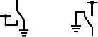
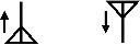
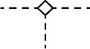
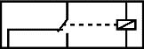
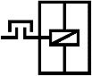
Functional Serial Data Communication

This icon is used to show the technician that the serial data circuit detail is shown incomplete. It also provides an active link to the Data Communication Schematics were the circuit is shown complete.


Switch Position Icons


Symbol


Description


1989016


Generic Up Arrows


1990554


Generic Down Arrows


1990555


Generic Left Arrows


1990556


Generic Right Arrows


1990557


Generic Express Down Arrows


1990558


On/Off Icon


1990559


Generic Lock Icon


1990560


Generic Unlock Icon


1989018


Generic Window Switch Positions– 4 Door


1989020


Generic Window Switch Positions– 2 Door


Module Circuit Function Icons


Symbol


Description


1988774


I/O Pull-Down Resistors (−)


1990567


I/O Pull-Up Resistors (+)


1988775


I/O High-Side Drive Switch (+)


1990568


I/O Low-Side Drive Switch (+)


1990570


I/O Bidirectional Switch (+/−)


1990571


Pulse-Width Modulation Symbol


1990573


Battery Voltage


1990574


Ignition Voltage


1990576


Voltage Reference


1990577


A/C Voltage


1988986


Low Reference


1990578


Ground


1990579


Serial Data


1988973


Aerial Signal– In


1988974


Aerial Signal– Out


2161152


Brake Apply


Harness Components


Symbol


Description


1988731


Fuse


1988733


Fuse Supplied by a Relay


1988740


Circuit Breaker


1988745


Fusible Link


1988987


Ground


1988746


Case Ground


1988977


Inline Harness Connector


1990974


Inline Harness Connector


1990975


Pigtail Connection


1990976


Pigtail Connection


1990977


Provisional or Diagnostic Connector


1990978


Blunt Cut Wire


1988980


Incomplete Physical Splice


1988981


Complete Physical Splice– 2 Wires


1988982


Complete Physical Splice– 3 or more wires


1990979


Wire Crosses


1988988


Twisted Wires


1988990


Shield


1990980


Circuit References


1990981


Circuit Continuation Arrowheads


1988983


Option Breakpoint


1988984


Ground Circuit Connection


1988985


Connector Shorting Clip


Component Parts


Symbol


Description


1988694


Partial Component

When a component is represented in a dashed box, the component or its wiring is not shown in its entirety.


1988698


Entire Component

When a component is represented in a solid box the component or its wiring is shown in its entirety.


1988712


Connector Directly Attached to Component


1988715


Pigtail Connector


Switches and Relays


Symbol


Description


1991015


Accessory Power Outlet


1991016


Cigar Lighter


1988991


Switch– 2 Position Normally Open


1988992


Switch– 2 Position Normally Closed


1988993


Switch– Rocker


1991017


Switch– Contact Plate (1 Wire)


1988994


Switch– Contact Plate (2 Wire)


1991018


Switch– 3 Position


1988995


Switch– 4 Position


1991019


Switch– 5 Position


1991021


Switch– 6 Position


1988997


Switch Actuator– Push (Momentary)


1988998


Switch Actuator– Push (Latching)


1988999


Switch Actuator– Pull (Momentary)


1989000


Switch Actuator– Pull (Latching)


1989001


Switch Actuator– Rotate (Momentary)


1989002


Switch Actuator– Rotate (Latching)


1989003


Switch Actuator– Slide (Momentary)


1989004


Switch Actuator– Slide (Latching)


1989007


Switch Actuator– Pressure (Momentary)


1989010


Switch Actuator– Temperature (Momentary)


1989013


Switch Actuator– Volume (Latching)


1988975


4-Pin Single Pole/Throw Relay– Normally Open


1990539


5-Pin Relay– Normally Closed


Devices and Sensors


Symbol


Description


1988751


Battery


1988753


Battery Assembly– Hybrid


1988717


Single Filament Light Bulb


1988719


Double Filament Light Bulb


1988722


Light Emitting Diode (LED)


1988725


Photo Sensor


1990988


Gauge


1988776


Diode


1988748


Capacitor


1988755


Resistor


1988759


Variable Resistor


1990991


Variable Resistor– NTC


1990992


Breakable Wire


1988778


Heating Element


1988771


Position Sensor


1988773


Pressure Sensor


1990993


Knock Sensor


1990994


Inductive Type Sensor– 2-Wire


1990996


Inductive Type Sensor– 3-Wire


1990998


Hall Effect Sensor– 2-Wire


1990999


Hall Effect Sensor– 3-Wire


1991000


Oxygen Sensor– 2-Wire


1991001


Heated Oxygen Sensor– 4-Wire


1988970


Solenoid– Actuator


1988971


Solenoid– Valve


1988972


Clutch


1988779


Motor


1991003


Motor with PTC


1988729


Antenna


1991005


Speaker


1991006


Horn


1991007


Microphone


1991008


Airbag


1991009


SIR Coil


1991010


SIR Impact Sensor


Vehicle Zoning Strategy - Passenger Car > < Master Electrical Schematic Icons