|
Cylinder Head, Remove and Install (Z 17 DTH, with
AC, LHD)
 Remove Remove
Note: Before the oil
change, the customer should be informed of the ECOService-Flex and
ECOService options.
Important: On vehicles with ESP -
the steering angle sensor loses its basic adjustment each time the
battery is disconnected. It must be recalibrated
|
| 2. |
Disconnect battery
|
| 4. |
Detach front right wheel
|
| 5. |
Drain coolant
| • |
Place collecting basin underneath.
|
|
|
|
| 6. |
Remove air cleaner housing
|
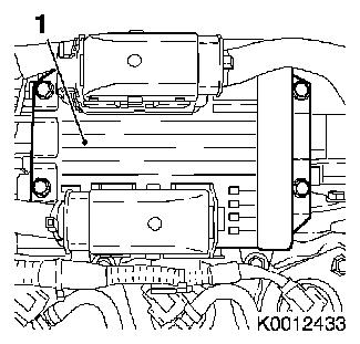
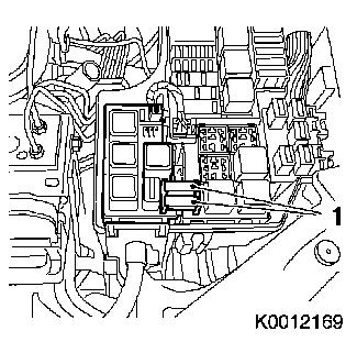
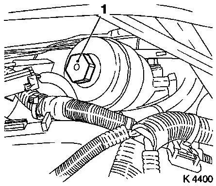
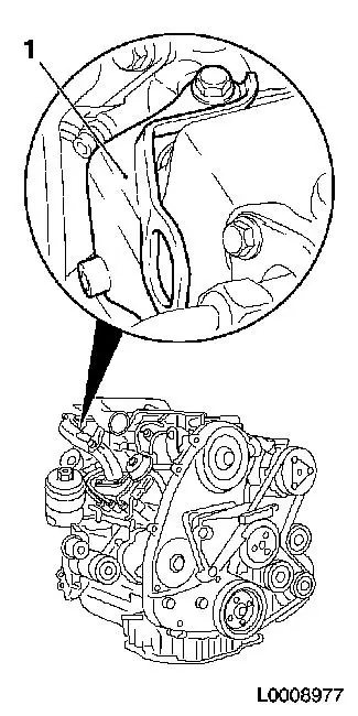
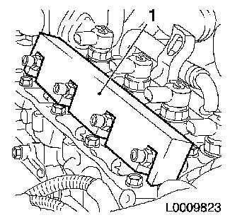
| 7. |
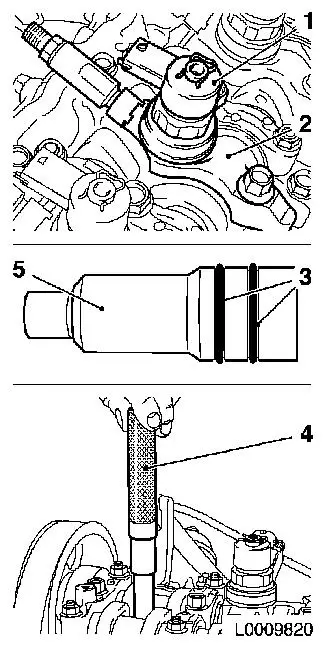
Remove engine control unit (1)
| • |
Disconnect 2 wiring harness plugs
|
|
|
|
| 8. |
Detach engine control unit bracket
|
| 9. |
Detach bracket of engine control unit bracket
|
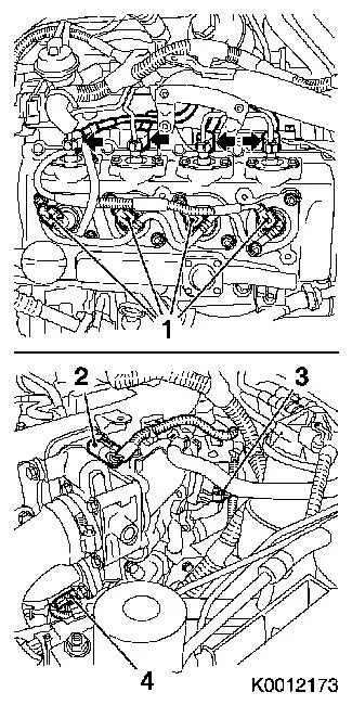
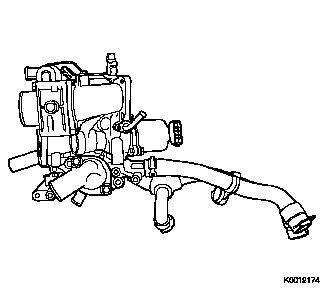
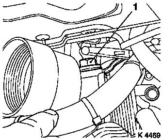
| 10. |
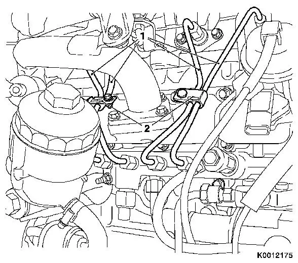
Remove engine management wiring harness
| • |
Disconnect wiring harness plug
| – |
Coolant temperature sensor (4)
|
| – |
Throttle valve module (2)
|
| – |
Exhaust gas recirculation valve (3)
|
| – |
Changeover valve solenoid valves
|
|
|
|
|
| 11. |
Detach intercooler connection hose to throttle valve module at
throttle valve module
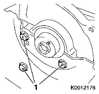
|
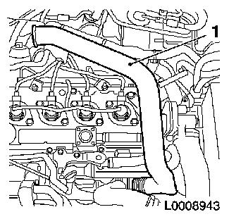
| 12. |
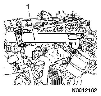
Remove air intake pipe (1)
| • |
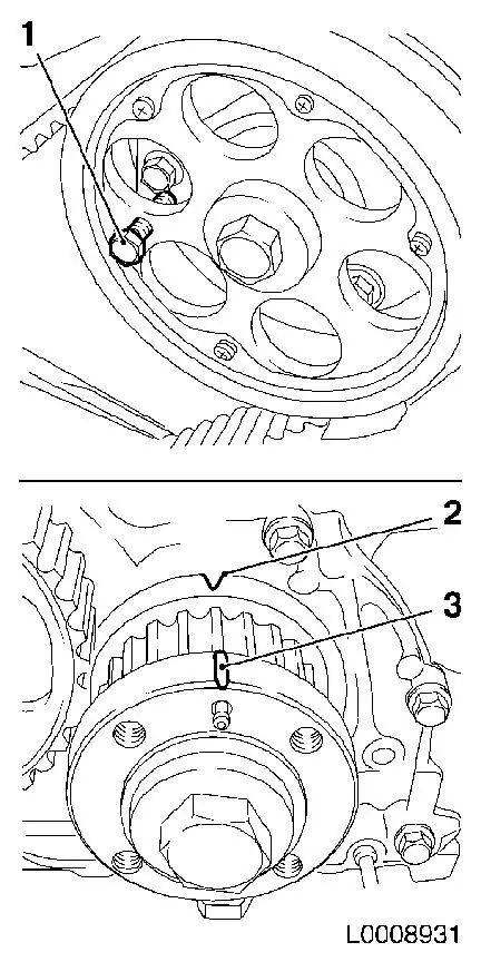
Detach engine vent hose
|
|
|
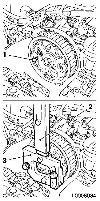
|
| 13. |
Remove charge air pipe (1)
| • |
Unscrew and remove 3 stud bolts
|
|
|
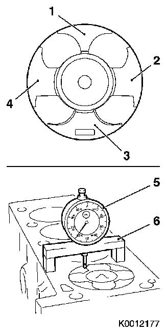
|
| 14. |
Remove rear left engine transport shackle
|
| 15. |
Detach thermostat housing
| • |
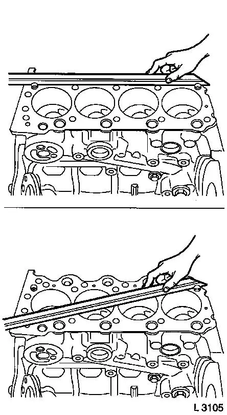
Detach coolant hose, return, exhaust gas recirculation
valve
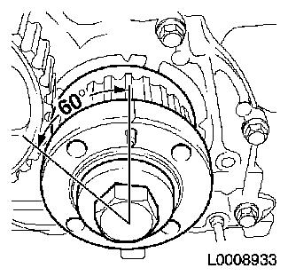
|
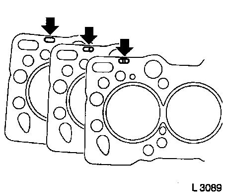
| • |
Disconnect upper radiator hose
|
|
|
|
| 16. |
Detach refrigerant line from compressor
|
| 17. |
Loosen upper oil dipstick guide tube
|
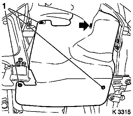
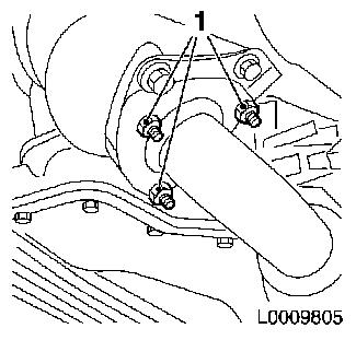
| 18. |
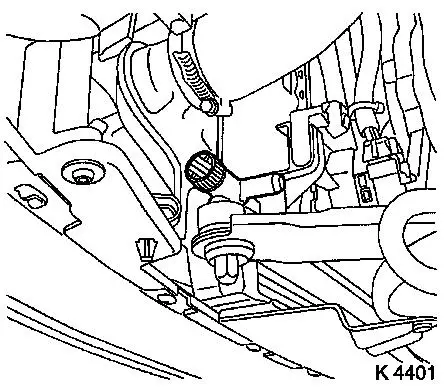
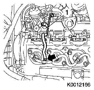
Detach cooling module wiring harness
| • |
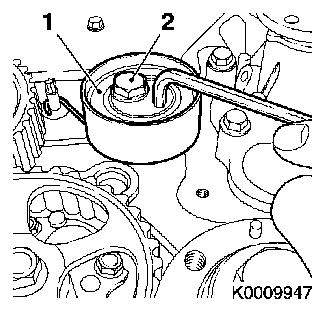
Draw 2 series fuses (1)
|
| • |
Disconnect ground cable (arrow)
|
|
|
|
| 19. |
Disconnect compressor wiring harness plug
|
| 20. |
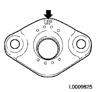
Detach upper charge air hose
| • |
Open quick-release fitting
|
|
| 21. |
Detach front panelling
|
| 22. |
Remove right front wheel
|
| 23. |
Remove ribbed V-belt cover
|
|
|
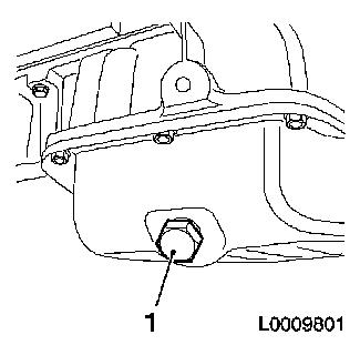
| 25. |
Close coolant drain bolt
|
| 26. |
Drain engine oil
| • |
Place collecting basin underneath.
|
|
|
|
| 28. |
Disconnect lower radiator hose
|
| 29. |
Disconnect refrigerant line
|
| 30. |
Detach lower charge air hose
| • |
Open quick-release fitting
|
|
| 32. |
Loosen cooling module bracket
|
|
|
| 33. |
Remove cooling module
Note: Second person
required
|
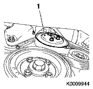
| 34. |
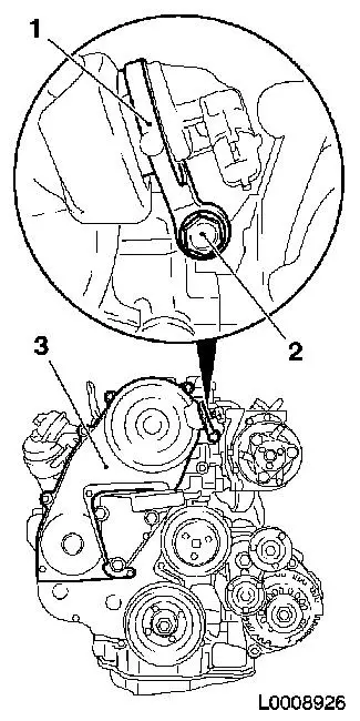
Loosen coolant pump ribbed V-belt pulley (1)
|
|
|
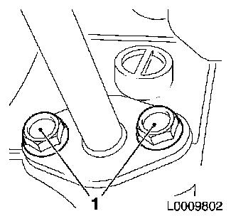
| 36. |
Detach 2x vacuum line
|
| 37. |
Remove front exhaust pipe
|
|
|
| 38. |
Disconnect turbocharger/intercooler connection hose
|
| 39. |
Remove compressor
| • |
Detach refrigerant line
|
|
| 40. |
Remove compressor support
|
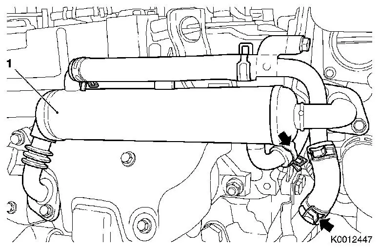
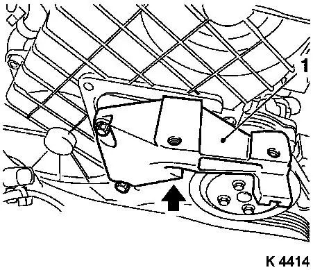
| 41. |
Detach EGR cooler (1)
| • |
Release 2 clamps (arrows)
|
|
|
|
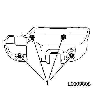
| 42. |
Detach exhaust manifold heat shield
|
|
|
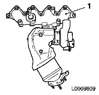
| 43. |
Remove exhaust manifold (1) with turbocharger
| • |
Detach turbocharger oil feed line
|
| • |
Detach turbocharger oil return line
|
| • |
Detach wastegate unit vacuum line
|
|
|
|
| 44. |
Remove oil dipstick guide tube
|
|
|
| 45. |
Detach coolant pipe bracket from cylinder head
|
| 47. |
Oil filter housing return hose
|
|
| 48. |
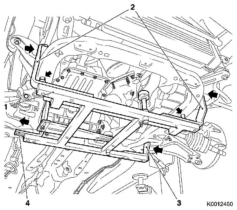
Attach KM-6394
| • |
Position KM-6394 (1) at the front on
the front axle body
Note: Both locating
pins (arrows) must be seated in the holes in the front axle
body
|
| • |
Push front bracket (2) in the direction of the arrow
|
| • |
Place rear bracket (4), right hand side, on front axle body
|
| • |
Attach rear bracket (3), left hand side
|
|
|
|
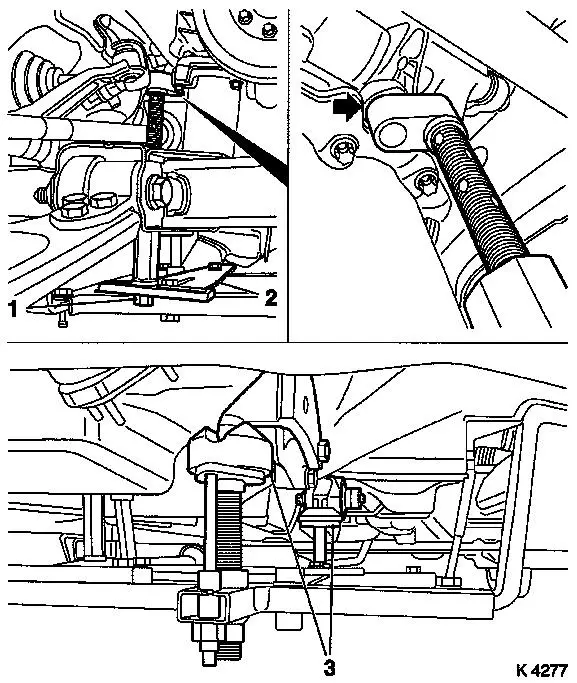
| 49. |
Install support
| • |
On KM-6394
| – |
Adjust bracket (2) for support
|
|
|
| 50. |
Adjust 3x support
| • |
Transmission side
Note: Turn spindles
until mounts (3) are positioned at guide journals free of play
|
| • |
Engine timing side
| – |
Insert journal of the support in the bore of the cylinder block
free of play (arrow)
|
|
|
|
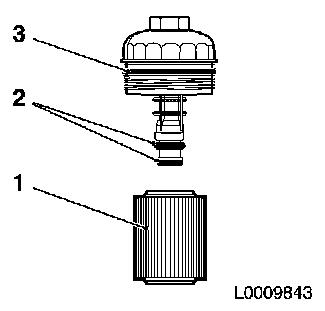
| 52. |
Remove oil filter element
| • |
Unscrew oil filter housing cover (1)
|
|
|
|
| 53. |
Remove oil filter housing
| • |
Detach coolant hose from cylinder head
|
| • |
Place collecting basin underneath.
|
|
|
|
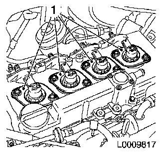
|
| 54. |
Remove 2 high pressure line spacers (2)
Note: Mark installation
position
|
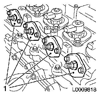
| 55. |
Detach 4 high-pressure lines (1)
|
|
| 56. |
Detach outer fuel return line (1)
|
|
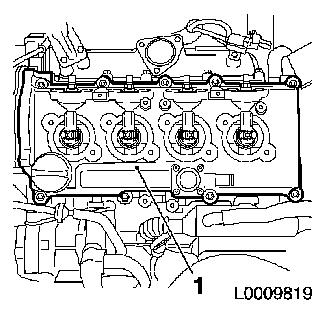
|
| 57. |
Remove vacuum line bracket
|
| 58. |
Remove wiring trough
| • |
Detach wiring harness bracket
|
| • |
Disconnect wiring harness plug of dynamic oil level check
sensor
|
| • |
Electrically disconnect alternator
| – |
Disconnect wiring harness plug
|
|
|
| 59. |
Disconnect vacuum hose for vacuum unit switchover valve
|
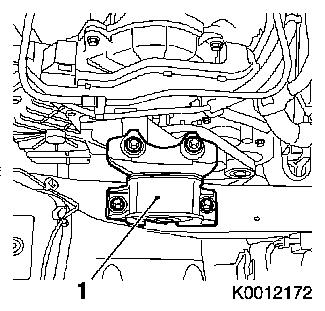
| 60. |
Remove right engine damping block (1)
|
|
|
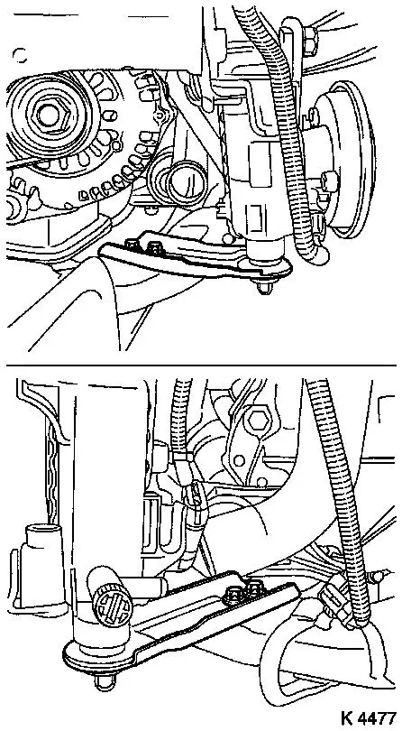
| 61. |
Detach right engine bracket (1)
| • |
Unscrew 3 bolts
Note: Lower bolt cannot
be removed
|
| • |
With right engine bracket adapter
|
|
|
|
| 62. |
Remove camshaft sensor (1)
|
| 63. |
Remove upper toothed belt cover (3)
Important: Take care not to
damage the increment counter on the camshaft sprocket when removing
the upper toothed belt cover
|
| • |
Unscrew 8 bolts
Note: Note dissimilar
bolt lengths
|
|
|
|
| 65. |
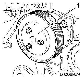
Detach coolant pump ribbed V-belt pulley (1)
|
|
|
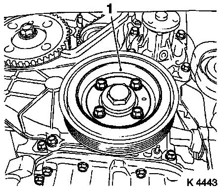
| 66. |
Remove torsional vibration damper (1)
|
|
|
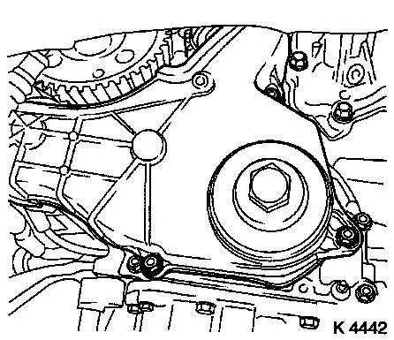
| 67. |
Detach lower part of toothed belt cover
|
|
|
| 68. |
Remove right engine bracket
Note: Remove together
with engine bracket adapter
|
| 69. |
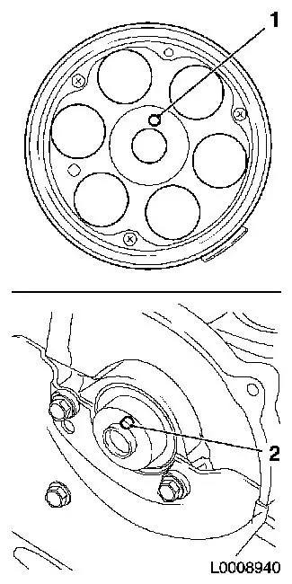
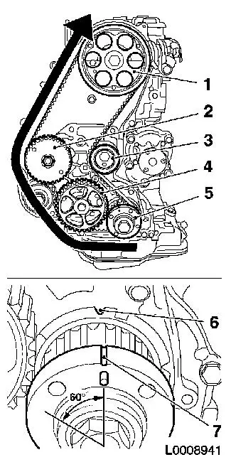
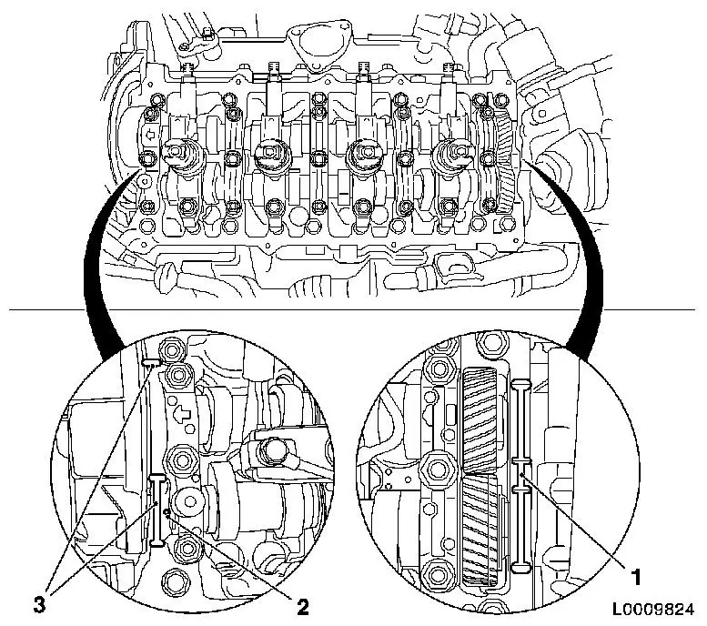
Set 1st cylinder to TDC
| • |
Turn crankshaft evenly until TDC fixing bolt (1) can be screwed
in
Note: Mark (3) on
toothed belt drive gear must align with mark (2) on oil pump
cover
|
|
|
|
| 70. |
Remove toothed belt
Note: Mark running
direction.
| • |
Loosen toothed belt tension roller (1)
|
| • |
Pretension toothed belt tension roller in direction of
arrow
|
| • |
Secure toothed belt tension roller in pretensioned position
|
|
|
|
| 71. |
Turn crankshaft
| • |
Rotate crankshaft against the direction of engine rotation to
60° BTDC
|
|
| 73. |
Detach camshaft pulley
| • |
Unscrew TDC fixing bolt (1)
|
| • |
Use KM-6347 (3) KM-956-1 (2)
|
|
|
|
| 74. |
Loosen rear toothed belt cover
|
|
|
| 75. |
Detach 4 oil leak hoses from injectors
|
| 76. |
Remove rear right engine transport shackle (1)
|
|
|
| 77. |
Remove 4 injector connection seals (1)
|
|
|
| 78. |
Remove 4 injector seals (1)
|
|
|
| 79. |
Remove camshaft housing cover
|
|
|
| 80. |
Remove 4x injector (1)
Note: Mark the
injectors. If the heat insulation sleeve (5) is also drawn out when
an injector is removed, the gaskets (3) must be replaced and the
heat insulation sleeve must be driven into the cylinder head using
KM-6357 (4).
|
|
|
| 81. |
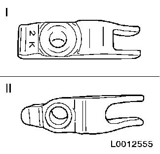
Check injector bracket
Note: If an old
injector bracket was installed, it must be replaced with a new
one
- New injector bracket
- Old injector bracket
|
|
|
| 82. |
Remove front left engine transport shackle
|
|
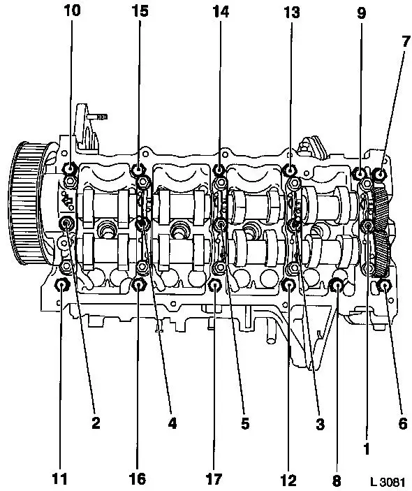
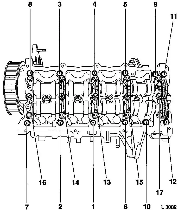
| 83. |
Remove camshaft housing cover
| • |
Unscrew 17x bolt
| – |
Loosen 1/2 turn in the order illustrated, then unscrew
|
|
|
|
| 84. |
Remove 16 cup tappets
Note: Note order and
installation position.
|
|
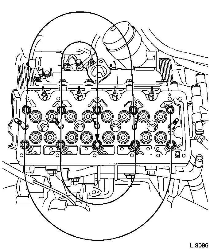
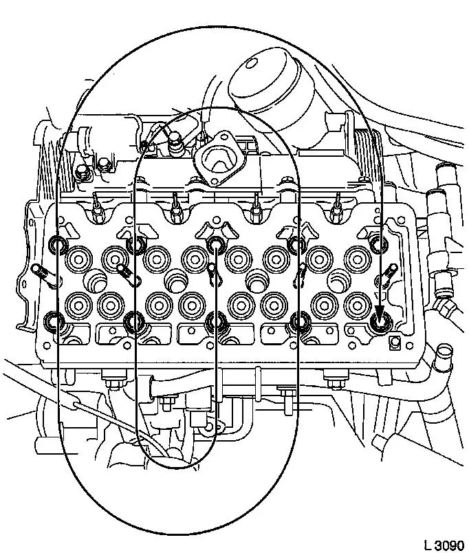
| 85. |
Unscrew 10 cylinder head bolts
Note: Loosen bolts 1/2
to 1 turn in a spiral in the order illustrated.
|
|
| 86. |
Remove cylinder head
Note: 2. Fitter
required
| • |
Remove cylinder head gasket
|
|
| 87. |
Clean sealing surfaces
| • |
Cylinder head, cylinder block, camshaft housing, camshaft
housing cover, exhaust manifold, pre-catalytic converter,
thermostat housing
|
|
| 88. |
Check for plane surface
| • |
Cylinder head, cylinder block
|
| • |
With straightedge, feeler gauge
|
|
|
|
| 89. |
Measure piston projection
| • |
Insert MKM-571-B (5) into KM-301 (6)
|
| • |
Set dial to zero
| – |
Place probe on cylinder block
|
|
| • |
Measure piston projection on all four pistons
| – |
Carry out measurement on two different locations (1 and 2) or
(3 and 4)
|
| – |
Determine high point by turning crankshaft
|
|
|
|
|
| 90. |
Rotate crankshaft approx. 60° against direction of engine
rotation
|
|
|
Important: The largest determined
piston projection determines the selection of the cylinder head
gasket with appropriate identification.
|
| 91. |
Replace cylinder head gasket
|
Piston projection
|
Thickness of cylinder head gasket
|
Code
|
|
0.630 – 0.696 mm
|
1.350 mm
|
no hole
|
|
0.697 – 0.763 mm
|
1.400 mm
|
one hole
|
|
0.764 – 0.830 mm
|
1.450 mm
|
two holes
|
| • |
Lay cylinder head gasket in place
|
|
|
|
 Install
| 92. |
Attach cylinder head
Note: 2nd mechanic is
required. Note guide bushings
|
|
| 93. |
Fasten cylinder head
| • |
Tighten 10 new bolts 39.2 Nm + 60°
+ 60°
Note: Tighten in a
spiral from inside to outside in the order shown with MKM-610 in combination with KM-470-B .
|
|
|
| 94. |
Insert cup tappets
Note: Observe
allocation.
| • |
Put the camshaft housing gasket into position
|
|
|
| 95. |
Install camshaft housing
| • |
Replace gasket
Note: Note tightening
sequence.
| – |
Tighten 12 bolts 21.6 Nm
|
| – |
Tighten 5 bolts 26.5 Nm
|
|
|
|
| 96. |
Attach rear toothed belt cover
|
Warning: The different camshaft
sprockets (with different part numbers) have different torques for
the camshaft sprocket bolt.
|
| 97. |
Attach camshaft sprocket with part number 97320335
| • |
Camshaft journal (2) must engage in the bore in the camshaft
sprocket (1)
|
| • |
Use KM-6347 in combination with KM-956-1
|
| • |
Install TDC-fixing bolt
|
|
| 98. |
Attach camshaft sprocket with part number 98021306
| • |
Camshaft journal (2) must engage in the bore in the camshaft
sprocket (1)
|
| • |
Use KM-6347 in combination with KM-956-1
|
| • |
Install TDC-fixing bolt
|
|
|
|
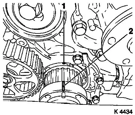
| 100. |
Rotate crankshaft to 1st cylinder TDC
| • |
Mark on toothed belt drive gear (2) must align with cast lug
(1) on oil pump cover
|
|
|
|
| 101. |
Install toothed belt
Note: TDC locking bolt
must be installed in the camshaft sprocket and marking (6) and (7)
must align.
| • |
Position toothed belt
| – |
Toothed belt must be tensioned in the direction of the arrow
from the toothed belt drive gear (5) via the oil pump drive gear
(4), via the high pressure pump drive gear (2) to the camshaft
sprocket (1)
|
|
| • |
Loosen toothed belt tension roller (3)
|
| • |
Remove TDC locking bolt
|
| • |
Rotate crankshaft 60° against direction of engine
rotation
|
| • |
Tighten toothed belt tension roller 38Nm
|
|
|
|
| 102. |
Timing, Check
| • |
Turn crankshaft approx. 780° in direction of engine
rotation
|
| • |
Mark on toothed belt drive gear (3) must align with cast lug
(2) on oil pump cover
|
| • |
Screw in TDC fixing bolt (1). If the TDC fixing bolt cannot be
screwed in, basic adjustment must be repeated.
|
| • |
Unscrew TDC fixing bolt
|
|
|
|
| 103. |
Attach right engine bracket
| • |
Insert lower bolt
| – |
Into right engine bracket and right engine bracket adapter
|
|
| • |
Fit right engine bracket with adapter
|
|
| 104. |
Attach lower part of toothed belt cover
|
| 106. |
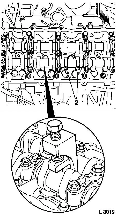
Turn crankshaft
| • |
Turn crankshaft until cam pairs (1) and (2) point upwards
|
|
|
|
| 107. |
Check valve clearance
| • |
Using feeler gauge
Note: The valve play is
checked on a cold engine at room temperature
| – |
Test values: Intake valves/Exhaust valves (0.35 – 0.45
mm)
|
|
|
| 108. |
Adjust valve clearance
| • |
Turn cup tappet until tappet groove points outwards
|
Important: Make sure that the
valves are not set when the piston is in "TDC". The valves could
strike the piston head
|
| • |
Press down cup tappets using KM-6090
Note: Note different
tool versions for intake and exhaust valves
| – |
Mark – IN = Intake side
|
| – |
Mark – EX = Exhaust side
|
|
|
| 109. |
Insert adjustment shim
| • |
Coat new shim with engine oil and insert in cup tappet with
identification mark facing downwards
|
|
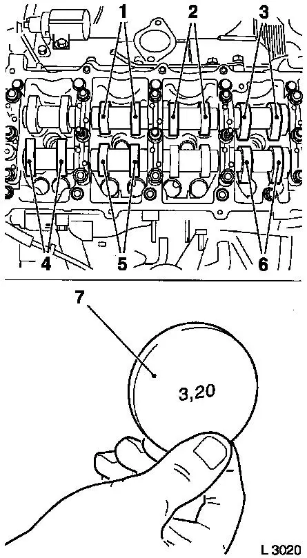
| 110. |
Turn crankshaft
| • |
In direction of engine rotation by 180°
| – |
Check and adjust valve pair (6) and (2)
|
|
| • |
In direction of engine rotation by 180°
| – |
Check and adjust valve pair (5) and (3)
|
|
| • |
In direction of engine rotation by 180°
| – |
Check and adjust valve pair (4) and (1)
Note: The clearance of
all adjusted valves must be re-checked
|
|
|
|
|
| 111. |
Detach accumulator
| • |
Unscrew 2x bolts 1 - 1 1/2 turns
|
|
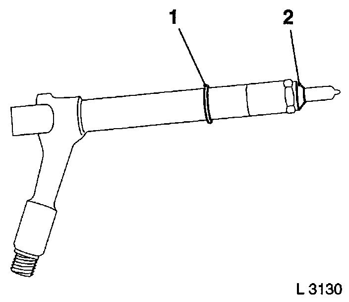
| 112. |
Replace 8 injector seals
| • |
4 copper seal rings (2)
|
|
|
|
| 113. |
Install 4 injectors
| • |
Install 4x brackets
| – |
Align injectors with EN-48560 (1)
|
|
|
|
|
| 114. |
Fasten 4x accumulator high pressure lines to injectors
| • |
Hand-tighten 8x union nuts
|
|
| 115. |
Fasten 4x injectors
| • |
Tighten 4 bolts in three stages
|
|
|
|
| 117. |
Remove 4x accumulator high pressure lines at injectors
| • |
Seal off connections of accumulator using suitable sealing
plugs
|
| • |
Seal off connections of injectors with protective caps
|
|
|
| 118. |
Install camshaft housing cover
Important: The oil hole (2) must
not be covered with adhesive sealing compound
|
| • |
Replace gasket
|
| • |
Apply adhesive sealing compound to sealing surfaces (1) and
(3)
|
|
|
| 119. |
Fit 4 injector seals
|
| 120. |
Fit 4 injector connection seals
| • |
Replace 4 gaskets
Note: Note installation
position (arrow)
|
|
|
|
| 121. |
Install upper toothed belt cover
| • |
Tighten 8 bolts 9.8 Nm
Note: Note dissimilar
bolt lengths
|
|
| 122. |
Fasten right engine bracket
| • |
Tighten 2 upper bolts 40 Nm
|
|
| 123. |
Install right engine damping block
| • |
At engine bracket adapter
| – |
Tighten 2 bolts 60 Nm + 30° +
15°
|
|
|
| 124. |
Install camshaft sensor
|
| 125. |
Attach wiring trough
| • |
Connect dynamic oil level check sensor wiring harness plug
|
| • |
Connect camshaft sensor wiring harness plug
|
| • |
Install wiring harness bracket
|
|
| 126. |
Attach vacuum line bracket
|
| 127. |
Connect vacuum hose to vacuum unit switchover valve
|
| 129. |
Fasten right engine bracket
| • |
Tighten lower bolt 40 Nm
|
|
| 132. |
Attach coolant pump ribbed V-belt pulley
|
| 133. |
Install torsional vibration damper
| • |
Tighten 4 bolts 19.6 Nm
|
|
| 135. |
Insert dipstick guide tube
|
| 136. |
Fasten lower dipstick guide tube
|
| 137. |
Install turbocharger with exhaust manifold
| • |
Attach wastegate unit vacuum line
|
| • |
Attach turbocharger oil return line
|
| • |
Attach turbocharger oil feed line
| – |
Tighten banjo bolt (M8) 20.6 Nm
|
|
| • |
Fasten pre-catalytic converter to bracket
|
|
| 138. |
Attach exhaust manifold heat shield
| • |
Tighten 4 bolts 11.8 Nm
|
|
| 139. |
Attach front exhaust pipe
| • |
Tighten 3 new nuts 25 Nm
|
|
| 140. |
Attach compressor support
| • |
Tighten 3 bolts 43.1 Nm
|
|
| 141. |
Fit compressor
| • |
Tighten 3 bolts 18.6 Nm
|
| • |
Attach refrigerant line
|
|
| 142. |
Attach 2x vacuum line
|
| 143. |
Connect alternator
| • |
Connect wiring harness plug.
|
|
| 144. |
Install front left engine transport shackle
|
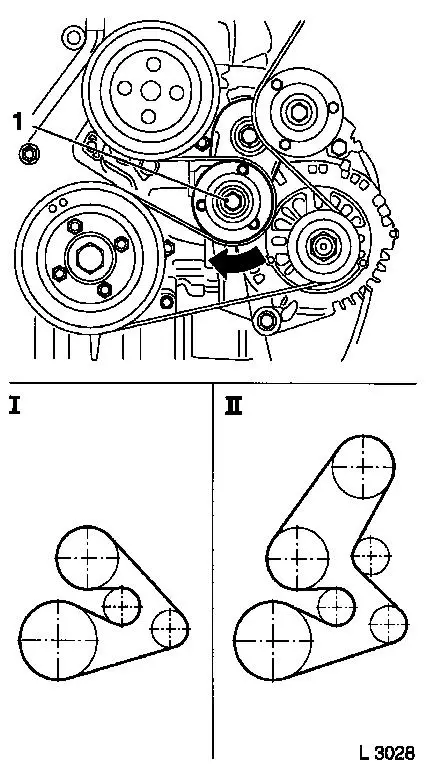
| 145. |
Install ribbed V-belt
Note: Note running
direction and installation position
| • |
Tension ribbed V-belt tensioner (1)
| – |
I Ribbed V-belt without AC
|
| – |
II Ribbed V-belt with AC
|
|
|
|
|
| 146. |
Fasten coolant pump ribbed V-belt pulley
|
| 148. |
Attach 4x fuel return line
| • |
To injector
| – |
Attach 4x retaining clamp
|
|
|
| 149. |
Attach outer fuel return line
| • |
Tighten banjo bolt 14.7 Nm
|
|
| 150. |
Fasten accumulator high pressure lines to injectors
| • |
Tighten 8x union nuts with KM-812 and
KM-6098
Note: First tighten
union nuts at the injectors and then at the accumulator
| |
Diameter
|
Torque
|
|
Version 1
|
6.00 mm
|
30 Nm
|
|
Version 2
|
6.35 mm
|
25 Nm
|
|
|
| 151. |
Install rear right engine transport shackle
|
| 152. |
Install oil filter housing
| • |
Tighten banjo bolt 25.5 Nm
|
|
| 153. |
Attach return hose of oil filter housing
|
| 154. |
Insert oil filter element (1)
| • |
Replace oil filter element
|
| • |
Install 3 new gaskets (2) and (3)
|
| • |
Tighten oil filter housing cover 25
Nm
|
|
|
|
| 155. |
Attach thermostat housing
|
| 156. |
Attach engine management wiring harness
| • |
Attach 14 wiring harness plugs
| – |
Coolant temperature sensor
|
| – |
Exhaust gas recirculation valve
|
|
| • |
Install wiring harness bracket
|
|
| 157. |
Install rear left engine transport shackle
| • |
Tighten 2 bolts 24.5 Nm
|
|
| 158. |
Install charge air pipe
| • |
Tighten 3 bolts 24.5 Nm
|
| • |
Tighten 3 stud bolts 24.5 Nm
|
|
| 159. |
Attach 2 wiring harness brackets
| • |
Route engine management wiring harness
|
|
| 160. |
Attach bracket of engine control unit bracket
|
| 161. |
Attach engine control unit bracket
|
| 162. |
Fit engine control unit
| • |
Connect wiring harness plug
|
| • |
Connect 2 combination plugs
|
|
| 163. |
Attach coolant pipe for EGR cooler
|
| 164. |
Attach EGR cooler
| • |
Tighten 4 bolts 28.5 Nm
|
|
| 165. |
Attach connection hose from turbocharger to charge air pipe
|
| 167. |
Install air intake manifold
|
| 168. |
Install cooling module
Note: Second person
required
|
| 169. |
Fasten cooling module bracket
|
| 170. |
Connect lower radiator hose
|
| 171. |
Attach refrigerant line
|
| 172. |
Install ribbed V-belt cover
|
| 173. |
Attach front panelling
|
| 176. |
Tighten front wheel 110 Nm
|
| 177. |
Connect upper radiator hose
|
| 178. |
Attach connection hose to throttle valve module
|
| 179. |
Attach turbocharger connection hose to intercooler
|
| 180. |
Attach cooling module wiring harness
|
| 181. |
Attach overflow hose
|
| 182. |
Fasten air intake pipe
| • |
Attach engine vent hose
|
| • |
Connect engine control unit wiring harness plug
|
|
| 183. |
Fasten upper dipstick guide tube
|
| 184. |
Connect compressor wiring harness plug
|
| 185. |
Attach refrigerant line at compressor
|
| 186. |
Install air cleaner housing
|
| 188. |
Calibrate steering angle sensor
| • |
Turn on ignition
Note: Turn the steering
wheel once from the right stop to left stop.
|
|
| 190. |
Top up engine oil
| • |
Observe specified engine oil quantity
|
| • |
Start engine and allow to run until oil pressure telltale
extinguishes.
|
| • |
Check engine oil level, if necessary correct.
|
|
| 191. |
Reset service interval using TECH 2
Note: If the customer
decides to have ECOService - attach TECH 2 and reprogram engine
control unit. Reset service interval using TECH 2 
|
| 192. |
Fill out the service sticker
|
| 193. |
Program volatile memory
|
| 194. |
Fill air conditioning system
|
Important: Wear protective
goggles
|
| 195. |
Carry out leak test on high pressure system
Note: Engine must be at
operating temperature
| • |
Carry out actuator test (fuel leak)
|
| • |
Inspect high pressure system for fuel leak
|
|
|
