|
Adjust timing (Y 17 DT, with air conditioning,
LHD)
Note: KM-6394 must be used from model year 04 instead of
KM-6169-1 .
Important: On vehicles from model
year 04 with ESP - the steering angle sensor loses its basic
adjustment each time the battery is disconnected. It must be
recalibrated.
|
| 2. |
Disconnect battery
|
| 3. |
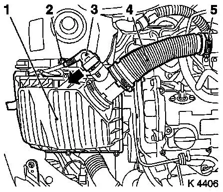
Remove air cleaner housing (1)
| • |
Disconnect wiring harness plug for hot film mass air flow meter
(3)
| – |
Release in direction of arrow
|
|
| • |
Remove air intake hose (4)
|
|
|
|
| 4. |
Detach front right wheel
|
| 6. |
Remove front right wheel
|
| 8. |
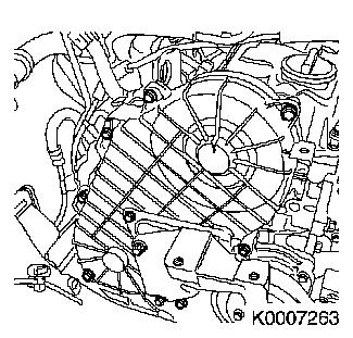
Detach ribbed V-belt cover
|
|
|
| 9. |
Remove ribbed V-belt
| • |
Tension ribbed V-belt tensioner in direction of arrow
Note: Mark direction of
rotation
|
|
|
|
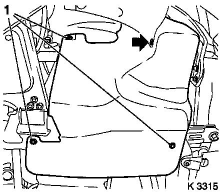
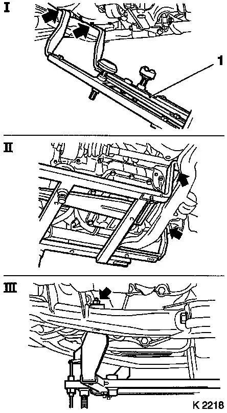
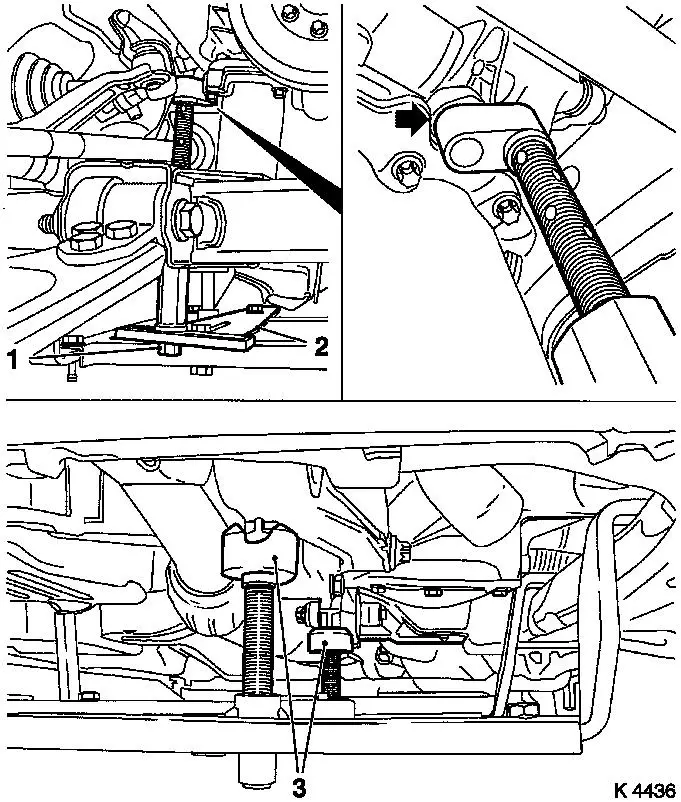
| 10. |
Attach KM-6169 (1)
| • |
Attach KM-6169 at left side of front
axle unit (arrows, fig.I)
Note: Guide pin must be
seated in bore in front axle body
|
| • |
Attach both right holders on the front axle body (arrows,
Illus. II).
Note: Guide pin must be
seated in bore in front axle body (arrow, Fig. III)
|
|
|
|
| 11. |
Install support
| • |
An KM-6169
| – |
Adjust bracket (2) for support
|
|
|
| 12. |
Adjust supports
| • |
Transmission side
Note: Turn spindles
until mounts (3) are positioned at guide journals free of play
|
| • |
Engine timing side
| – |
Insert journal of the support in the bore of the cylinder block
without play (arrow)
|
|
|
|
|
| 14. |
Remove right engine damping block
|
|

|
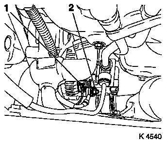
| 15. |
Detach alternator wiring harness
| • |
Disconnect wiring harness plug (1)
|
|
|
|
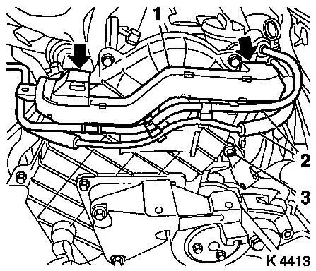
| 16. |
Remove wiring trough (1)
|
|
|
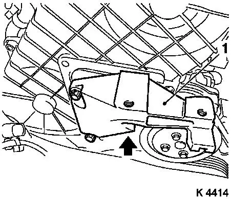
| 17. |
Detach right engine bracket (1)
|
|
|
| 18. |
Remove upper toothed belt cover
| • |
Remove 8 bolts
Note: Note dissimilar
bolt lengths
|
|
|
|
| 19. |
For toothed belt tension roller with leaf spring:
| • |
loosen toothed belt tensioner
| – |
Screw in bolt (M10) in lower bore (3) of toothed belt
tensioner
|
| – |
Remove tension spring (1)
|
|
|
|
|
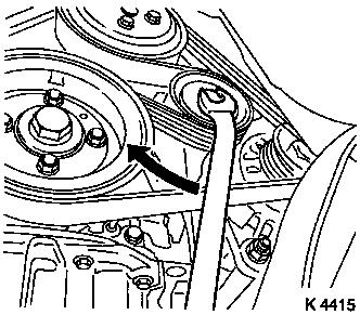
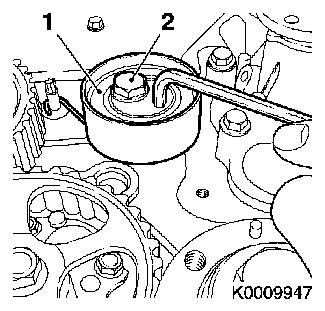
| 20. |
For toothed belt tension roller with spiral spring:
| • |
Loosen toothed belt tension roller (1)
| – |
Rotate toothed belt tension roller anticlockwise approx.
90°
|
|
|
|
|
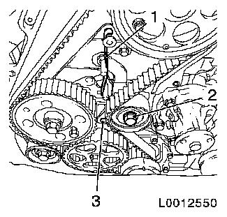
| 21. |
Correct timings
Note: Twist camshaft
gear and injection pump gear such that TDC fixing bolts can be
screwed in.
|
| 22. |
Install toothed belt
| • |
Position toothed belt
Note: Toothed belt must
be taut from toothed belt drive gear via oil pump drive gear and
injection pump drive gear
|
| • |
For toothed belt tension roller with leaf spring:
|
| • |
Unscrew TDC-fixing bolt
|
| • |
Rotate crankshaft 60° against direction of engine
rotation
|
| • |
Tighten bolt of toothed belt tension roller
| – |
For toothed belt tension roller with spiral spring 49 Nm
|
| – |
For toothed belt tension roller with leaf spring 38.2 Nm
|
|
| • |
For toothed belt tension roller with leaf spring: unscrew bolt
(M10) from lower bore of toothed belt tensioner
|
|
| 23. |
Timing, Check
| • |
Turn crankshaft approx. 780° in direction of engine
rotation
| – |
At toothed belt drive gear bolt
|
|
| • |
Torsional vibration damper marking must be in line with pin on
oil pump cover
|
| • |
Install TDC-fixing bolt
Note: If the TDC fixing
bolts cannot be screwed in, basic adjustment must be repeated
|
| • |
Unscrew TDC-fixing bolts
|
|
| 24. |
Attach right engine bracket
| • |
Insert lower bolt
| – |
Into right engine bracket and right engine bracket adapter
|
|
| • |
Insert right engine bracket, right engine bracket adapter,
upper part of toothed belt cover
|
| • |
Tighten 3 bolts( 40 Nm )
|
|
| 25. |
Fasten upper part of toothed belt cover
| • |
Tighten bolts ( 9.8 Nm )
Note: Note dissimilar
bolt lengths
|
|
| 26. |
Install right engine damping block
| • |
To side member
| – |
Tighten bolts ( 40 Nm )
|
|
| • |
On engine bracket
| – |
Tighten bolts ( 60 Nm + 30° +
15° )
|
|
|
| 28. |
Attach alternator wiring harness
|
| 32. |
Install ribbed V-belt
Note: Pay attention to
running direction and installation position
| • |
Release ribbed V-belt tensioner
|
|
| 33. |
Attach ribbed V-belt cover
|
| 35. |
Install right front wheel
|
| 37. |
Fasten right front wheel
| • |
Tighten bolts ( 110 Nm )
|
|
| 38. |
Install air cleaner housing
| • |
Fasten air intake hose.
|
| • |
Connect wiring harness plug to hot film mass air flow meter
|
|
| 40. |
Calibrate steering angle sensor
| • |
Switch on ignition
Note: Rotate the
steering wheel one time from its right-hand to its left-hand
stop.
|
|
| 41. |
Program volatile memories
|
|
