|
Engine With Manual Transmission, Remove and
Install (Z 17 DTH, with AC, LHD)
Important: In vehicles as of
model year 04 with ESP - every time the battery is disconnected,
the steering angle sensor loses its basic setting and must be
recalibrated
|
| 2. |
Disconnect battery
|
| 3. |
Detach steering intermediate shaft (1)
| • |
Remove lower clamp bolt (2)
|
| • |
Steering in straight ahead position
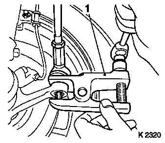
|
Important: Do not alter steering
wheel position
|
| • |
Remove steering intermediate shaft
|
|
|
|
| 4. |
Release 2x front wheel
|
| 5. |
Detach front panelling
|
| 7. |
Remove ribbed V-belt cover
|
|
|
| 8. |
Drain coolant
| • |
Place collecting basin underneath.
|
|
|
|
| 10. |
Remove air cleaner housing
|
| 12. |
Remove coolant compensation tank
|
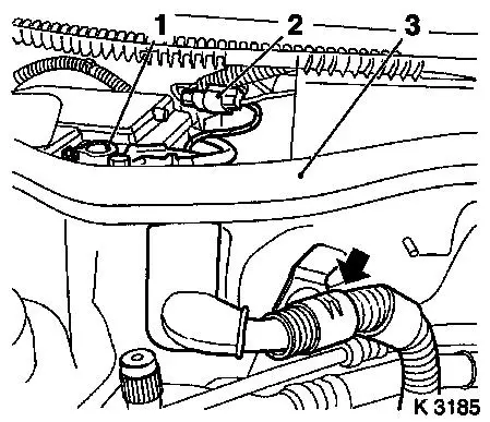
| 13. |
Detach starter/alternator wiring harness
| • |
Disconnect battery ground cable
|
| • |
Disconnect battery positive cable
|
| • |
Remove positive terminal (1)
|
| • |
Disconnect combination plug (2)
|
| • |
Remove cable harness and lay aside
|
|
|
|
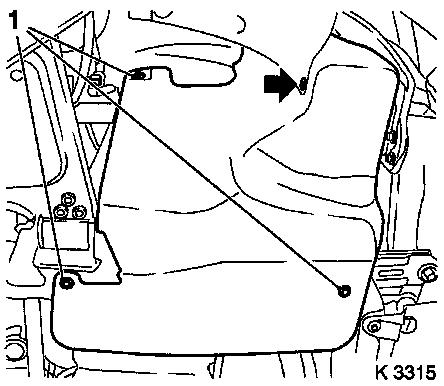
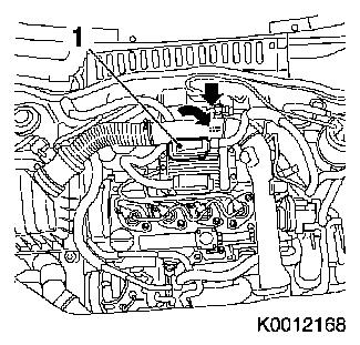
| 14. |
Remove engine management wiring harness
| • |
Disconnect 3 wiring harness plugs
| – |
From engine control unit (1)
|
| – |
2 combination plugs (arrows)
|
|
| • |
Unclip wiring harness and lay aside
|
|
|
|
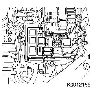
| 15. |
Detach cooling module wiring harness
| • |
Draw 2 series fuses (1)
|
| • |
Disconnect ground cable (arrow)
|
|
|
|
| 16. |
Detach 2x heating hose
|
| 17. |
Seal off brake fluid reservoir
|
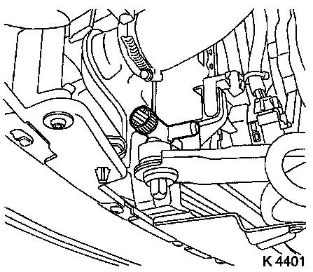
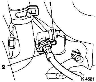
| 18. |
Detach high-pressure line from transmission
Note: Collect escaping
brake fluid
| • |
Pull off retaining clamp (1) and pull high-pressure line (2)
out of connecting piece for high-pressure line for central
release
|
| • |
Push retaining clamp into connector
|
|
|
|
|
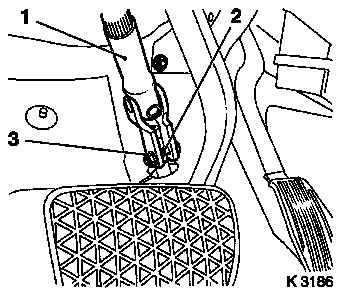
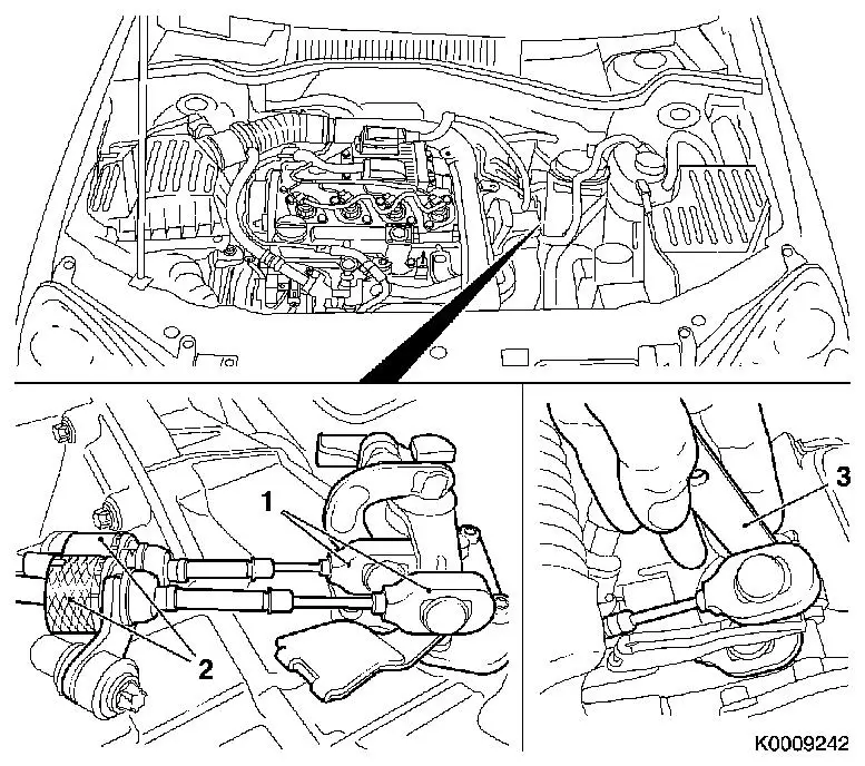
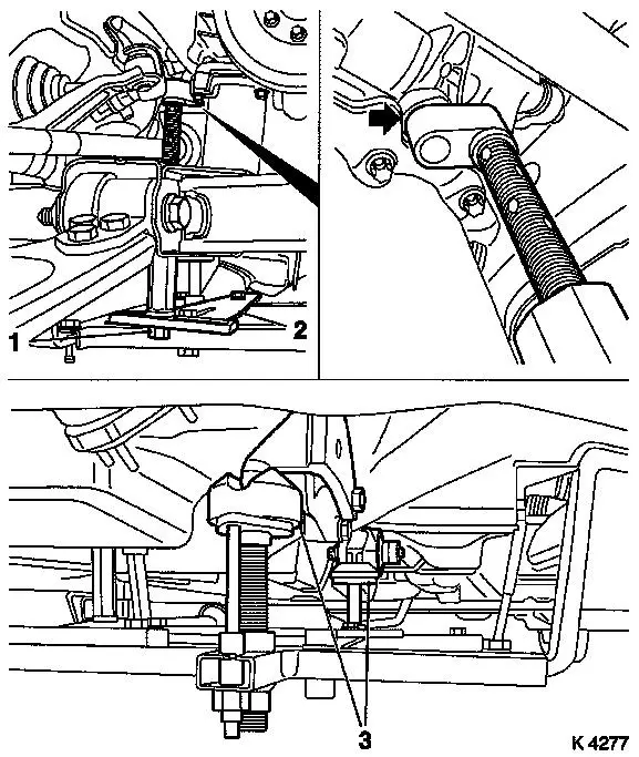
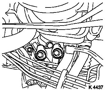
| 19. |
Disconnect shift cables (1) from transmission
| • |
Unclip shift cables from shift linkage lever using KM-6042 (3)
|
| • |
Unclip 2 from counterhold
Note: Push sleeve (2)
back and pull cable out of counterhold
|
|
|
| 20. |
Detach brake servo vacuum line
|
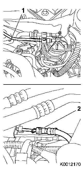
| 21. |
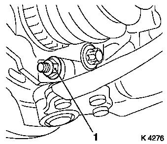
Detach fuel feed line (1)
|
| 22. |
Detach return fuel line (2)
| • |
Disconnect at quick-release fitting
|
|
|
|
| 23. |
Detach 2x refrigerant line
|
| 25. |
Close coolant drain bolt
|
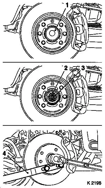
| 26. |
Release 2x axle shaft
| • |
Detach 2x protective cap (1)
|
| • |
Remove 2 cotter pins (2)
|
| • |
Unscrew 2x nut (3)
| – |
Counterhold using KM-468-B
|
|
|
|
|
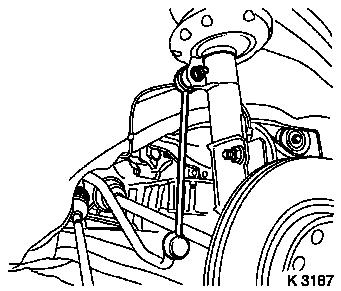
| 28. |
Detach 2x swing arm
| • |
From spring strut support tube
|
| • |
Unscrew 2 nuts
Note: Counterhold with
open-ended wrench
|
|
|
|
| 29. |
Detach 2 guide joints
|
|
|
| 30. |
Press out 2x axle shaft
|
Important: When removing the
centre muffler, a catalytic converter, an exhaust manifold or an
exhaust manifold with catalytic converter, the exhaust system piece
remaining in the vehicle must be prevented from swinging
uncontrollably. The exhaust system piece with the flex pipe inside
can be secured for this purpose using suitable means, such as a
wire on the vehicle underbody. Bends in the flex pipe with an angle
as little as 5 – 10 degrees from the intended installation
position may result in damage with subsequent total failure of the
flex pipe.
|
| 32. |
Remove exhaust system
| • |
Attach retaining rubber (5x)
|
| • |
Tether exhaust system laterally
Note: Second person
required
|
|
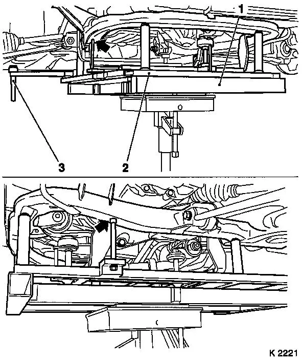
| 33. |
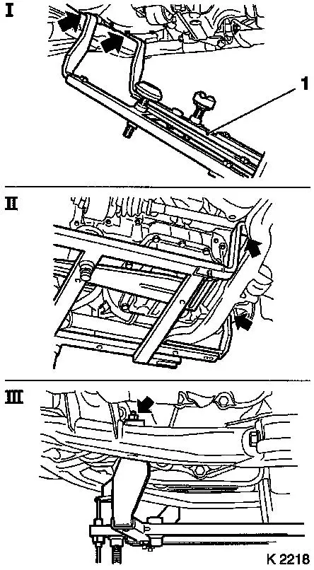
Attach KM-6394
| • |
Attach KM-6394 (1) at left side of
front axle body (arrows, fig. I)
Note: Guide pin must be
seated in bore in front axle body
|
| • |
Attach both right brackets on front axle body (arrows, Illus.
II)
Note: Guide pin must be
seated in bore in front axle body (arrow, Fig. III)
|
|
|
|
|
| 34. |
Install support
| • |
On KM-6394
| – |
Adjust bracket (2) for support
|
|
|
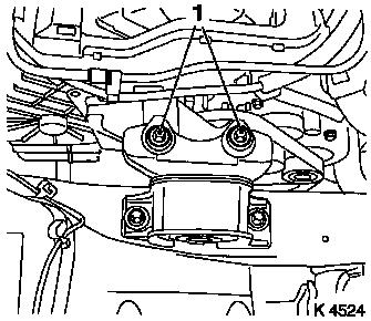
| 35. |
Adjust 3x support
| • |
Transmission side
Note: Turn spindles
until mounts (3) are positioned at guide journals free of play
|
| • |
Engine timing side
| – |
Insert journal of the support in the bore of the cylinder block
free of play (arrow)
|
|
|
|
| 37. |
Detach right engine damping block
|
|
|
| 38. |
Detach left engine damping block
|
|
|
| 40. |
Disconnect reversing light switch wiring harness plug
|
|
| 41. |
Insert hydraulic jack
|
| 42. |
Attach KM-6168
| • |
Apply KM-6168 (2)
Note: Lower body
positioning pins (3)
| – |
Onto KM-904
Note: Note differing
centring bolt diameters
|
|
| • |
Position KM-6168
| – |
Without play under front axle body
Note: Note centring
points in front axle body (arrows).
|
|
|
|
|
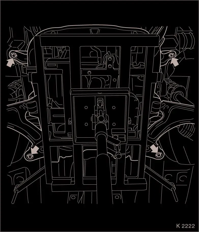
| 43. |
Release front axle body
Important: The removal of the
front axle body with an impulse or impact screwdriver is not
permitted
|
| • |
Unscrew 4 bolts (arrow)
|
|
|
Important: Carefully lower front
axle body with engine and transmission downwards out of engine
compartment. Do not damage attaching parts
|
| 44. |
Lower drive unit
Note: 2nd person
|
Important: Before installing the
front axle body, the lock nut threads must be checked for ease of
movement. Replace lock nuts if necessary
|
| 46. |
Check threads of 4 lock nuts
|
 Install
| 48. |
Raise drive unit
Note: Second person
required
Important: Carefully guide the
front axle body with engine and transmission up into the engine
compartment. Pay attention to the rear centring points. Do not
damage attaching parts
|
| • |
Steering shaft, upper radiator bracket
|
|
| 49. |
Fasten front axle body
Important: Do not use an impulse
or impact screwdriver to install the front axle body.
|
| • |
Tighten 4 new bolts 90 Nm + 45° +
15°
|
|
| 50. |
Remove hydraulic jack
|
| 52. |
Fasten left engine damping block
| • |
Tighten 2 bolts 80 Nm + 45° +
15°
|
|
| 53. |
Fasten right engine damping block
| • |
Tighten 2 bolts 60 Nm + 30° +
15°
|
|
| 57. |
Attach exhaust system
Note: Second person
required
|
| 58. |
Fasten front exhaust pipe
| • |
Tighten 3 new nuts 23.5 Nm
|
|
| 59. |
Connect reversing light switch wiring harness plug
|
| 62. |
Attach 2x guide joint
| • |
Tighten 2 new bolts 60 Nm
|
|
| 63. |
Attach 2x swing arm
| • |
Tighten 2 new nuts 65 Nm
Note: Counterhold with
open-ended wrench.
|
|
| 64. |
Attach 2 tie rods
| • |
Tighten 2 new nuts 35 Nm
|
|
| 65. |
Secure 2x axle shaft
| • |
Tighten 2 new nuts 120 Nm
|
| • |
Tighten 2 nuts 20 Nm + 90°
|
| • |
Install retaining split pins
Note: If necessary,
unscrew the nut until a pin hole aligns with the next castle nut
groove
|
|
| 66. |
Install ribbed V-belt cover
|
| 67. |
Detach front panelling
|
| 68. |
Attach 2x front wheel
|
| 69. |
Tighten 2 front wheels 110 Nm
|
| 70. |
Attach 2 refrigerant lines
|
| 71. |
Attach fuel return line
|
| 72. |
Attach fuel feed line
|
| 73. |
Attach brake servo vacuum line
|
| 74. |
Attach shift cables
| • |
Clip to shift linkage lever
|
| • |
Clip 2x in counterhold
Note: Pull back sleeve
and insert cable into counterhold. Shift cable at top, selector
cable at bottom.
|
|
| 75. |
Attach high pressure line
| • |
Insert high-pressure line into connecting piece for
high-pressure line for central release
Note: Connection must
noticeably engage.
|
|
| 76. |
Attach 2x heater hose
|
| 77. |
Attach cooling module wiring harness
|
| 78. |
Attach engine management wiring harness
| • |
Connect 3 wiring harness plugs
|
|
| 79. |
Attach starter/alternator wiring harness
|
| 80. |
Attach coolant compensation tank
|
| 81. |
Install air cleaner housing
|
| 82. |
Install steering intermediate shaft
Note: Steering wheel
and front wheels must be in straight-ahead position.
| • |
Push on steering intermediate shaft
Note: Steering can be
unlocked to facilitate work
|
Important: Only move steering
slightly
|
| • |
Replace nut (2) of lower clamp bolt
|
|
| 83. |
Bleed hydraulic clutch actuation 
|
| 87. |
Program volatile memory
|
| 88. |
Fill air conditioning system
|
|