|
Remove and install all pistons with con-rods (Z 14
XE, Z 16 YNG with air conditioning, RHD)
Warning: When using
vehicles running on natural gas, observe the particular procedures
and method of use, warning instructions and safety regulations.
Note: KM-6394 must be used as of model year 04 instead of
KM-6169-1 .
Note: The customer
should be informed of the choice between ECOService and
ECOService-Flex before the oil change.
Important: On vehicles as of
model year 04 with ESP - the steering angle sensor loses its basic
adjustment each time the battery is disconnected. It must be
recalibrated.
|
| 2. |
Disconnect battery
|
| 3. |
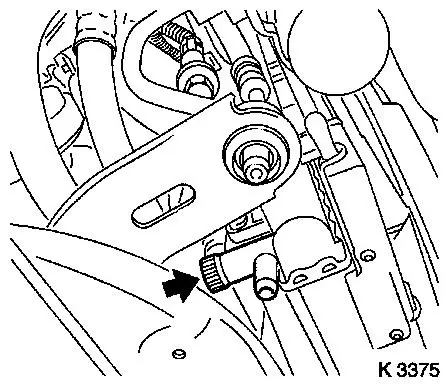
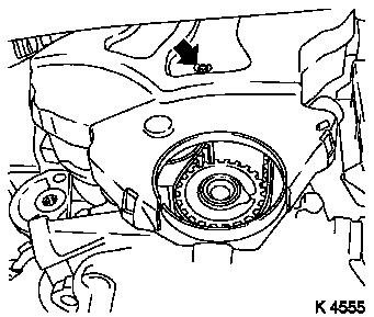
Drain coolant
| • |
Place collecting basin underneath.
|
| • |
Open drain bolt (arrow)
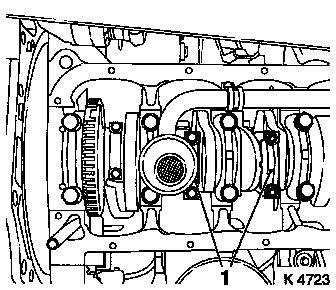
|
|
|
|
| 4. |
Remove engine cover.
| • |
Unscrew oil filler pipe cap
|
| • |
Screw on oil filler pipe cap
|
|
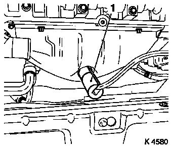
| 5. |
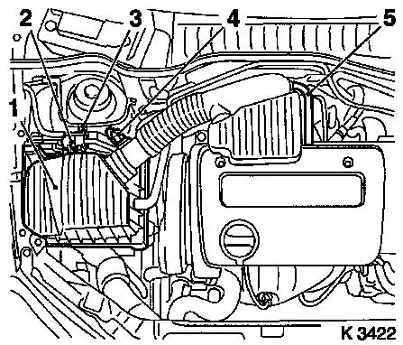
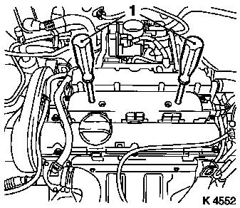
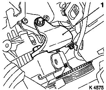
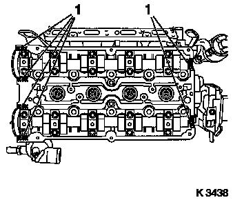
Remove air cleaner housing (1)
| • |
Disconnect wiring harness plug
| – |
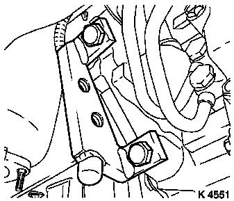
Intake air temperature sensor (4), tank vent valve (2)
|
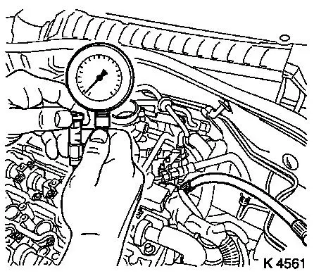
|
| • |
Remove air intake pipe
| – |
From throttle valve module
|
|
| • |
Detach engine vent hose (5)
|
|
|
|
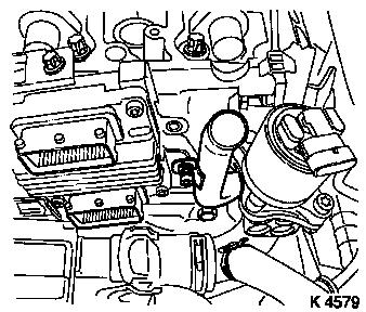
| 6. |
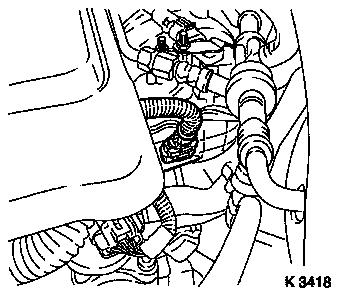
Remove ignition module
| • |
Disconnect wiring harness plug
|
Important: Do not tilt
|
| • |
Extract using KM-6009 (1)
|
|
|
|
| 7. |
Remove preheater hoses for throttle body module
|
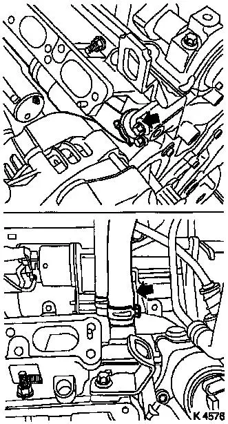
| 8. |
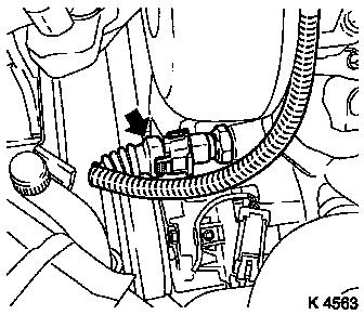
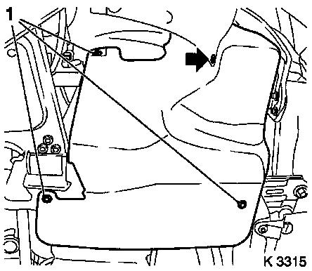
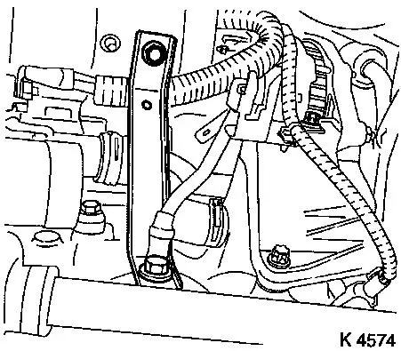
Remove coolant temperature sensor wiring harness plug
(arrow)
| • |
Release from rear of toothed belt cover
|
|
|
|
| 9. |
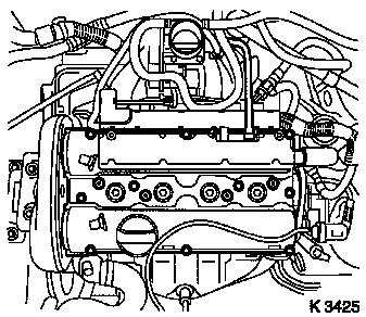
Remove cylinder head cover
| • |
Detach engine vent hose
|
| • |
Disconnect wiring harness plug for mixture regulating heated
oxygen sensor
|
|
|
|
| 10. |
Remove catalytic converter control oxygen sensor wiring harness
plug
| • |
Disconnect wiring harness plug
|
|
|
|
| 11. |
Loosen right front wheel.
|
| 13. |
Remove right front wheel.
|
| 15. |
Close coolant drain bolt
|
| 16. |
Drain engine oil
| • |
Place collecting basin underneath.
|
|
| 17. |
Remove ribbed V-belt cover
|
|
|
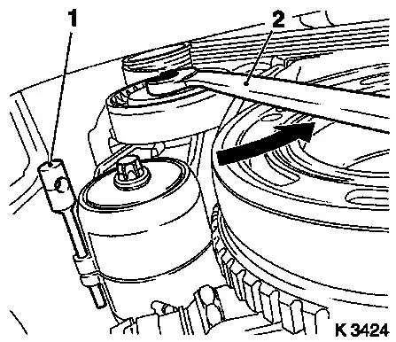
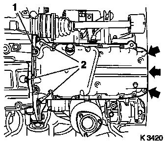
| 18. |
Remove ribbed V-belt
| • |
Tension ribbed V-belt tensioner in direction of arrow
| – |
Using KM-913-A (2) (SW 15)
|
|
| • |
Mark running direction.
|
|
|
|
| 19. |
Remove ribbed V-belt tensioner
| • |
Tension ribbed V-belt tensioner.
|
| • |
Release ribbed V-belt tensioner
|
|
|
|
| 20. |
Detach crankshaft ribbed V-belt pulley
| • |
Lever out front closure plug
|
|
|
|
| 21. |
Release lower part of toothed belt cover
| • |
Unclip from rear toothed belt cover
|
|
|
|
| 22. |
Install engine oil drain bolt
|
| 23. |
Loosen exhaust system
Important: When removing the
centre muffler, a catalytic converter, an exhaust manifold or an
exhaust manifold with catalytic converter, the exhaust system piece
remaining in the vehicle must be prevented from swinging
uncontrollably. The exhaust system piece with the flex pipe inside
can be secured for this purpose using suitable means, such as a
wire on the vehicle underbody. Bends in the flex pipe with an angle
as little as 5 – 10 degrees from the intended installation
position may result in damage with subsequent total failure of the
flex pipe.
|
| • |
Detach exhaust system
|
| • |
Detach front exhaust pipe
|
| • |
Suspend front exhaust pipe from left front axle body
|
|
| 24. |
Detach intake manifold support
|
|
|
| 25. |
Disconnect wiring harness plug for engine management
| • |
Crankshaft pulse generator, oil pressure switch
|
|
| 26. |
Remove oil pan
| • |
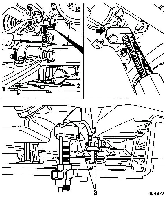
Lever out rear sealing plug (1)
|
| • |
Oil pump
| – |
Remove 3 bolts (arrows)
|
|
|
|
|
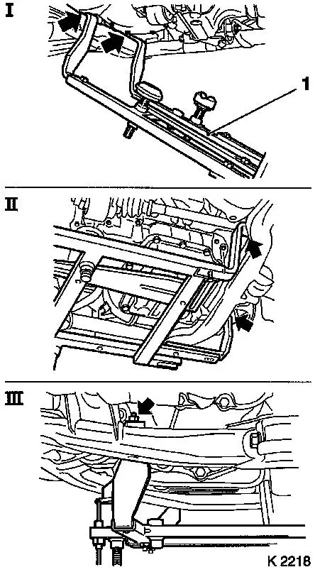
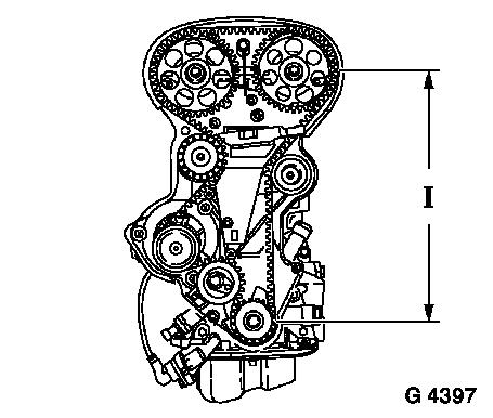
| 28. |
Attach KM-6169 (1)
| • |
Attach KM-6169 to left of front axle
body (arrows, illus. I)
Note: Guide pin must be
seated in bore in front axle body
|
| • |
Attach both right holders on the front axle body (arrows,
Illus. II).
Note: Guide pin must be
seated in bore in front axle body (arrow, Illus. III).
|
|
|
|
| 29. |
Install support
| • |
An KM-6169
| – |
Adjust bracket (2) for support
|
|
|
| 30. |
Adjust supports
| • |
Transmission side
Note: Turn spindles
until mounts (3) are positioned at the guide journals free of
play.
|
| • |
Engine timing side
| – |
Insert journal of the support in the bore of the cylinder block
without play (arrow)
|
|
|
|
|
| 32. |
Remove right engine damping block
| • |
Loosen engine bracket adapter
|
| • |
Loosen engine damping block
|
|
| 33. |
Remove upper part of toothed belt cover
| • |
Remove 3 bolts (arrows)
|
| • |
Unclip from rear toothed belt cover
|
|
|
|
| 34. |
Remove camshaft sensor (1)
| • |
Disconnect wiring harness plug
|
|
|
|
| 35. |
Remove lower part of toothed belt cover
| • |
Unclip from rear toothed belt cover
|
|
| 36. |
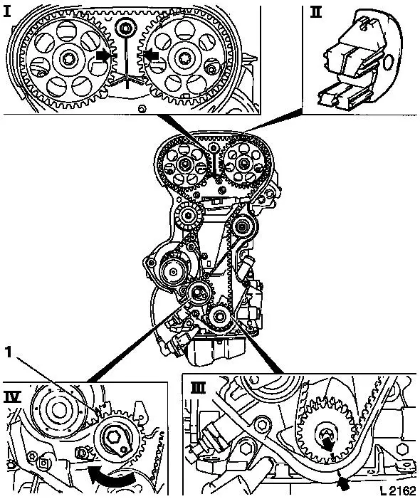
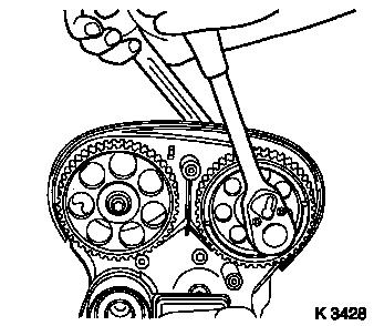
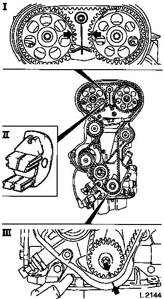
Set 1st cylinder to TDC of combustion stroke
| • |
Install crankshaft V-belt pulley bolt
|
| • |
Set crankshaft to mark.
| – |
Turn crankshaft evenly
Note: Marks on drive
gear toothed belt and rear toothed belt cover must align (III).
|
|
| • |
Fix camshaft sprockets in position.
Note: Marks must be
opposite one another and aligned with the top edge of the cylinder
head (I)
|
|
| 37. |
Remove toothed belt
| • |
Release toothed belt tension roller (IV)
Note: Mark running
direction.
| – |
Turn adjusting eccentric in direction of arrow (clockwise)
until pointer (1) of the toothed belt tension roller is located
just before left stop.
|
|
|
|
|
| 38. |
Remove camshaft sprockets
| • |
Remove 2 bolts
| – |
Counterhold camshafts at hexagonal section
|
|
|
|
|
| 39. |
Remove intake side toothed belt guide roller
|
| 40. |
Remove exhaust side toothed belt guide roller
|
| 41. |
Remove right engine bracket (3)
|
| 42. |
Remove toothed belt tension roller
|
|
|
| 43. |
Remove toothed belt drive pulley
| • |
Unscrew crankshaft ribbed V-belt pulley bolt
|
| • |
Remove toothed belt drive pulley
|
|
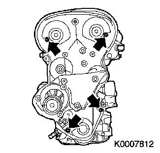
| 44. |
Remove rear of toothed belt cover
| • |
Remove 4 bolts (arrows)
|
|
|
|
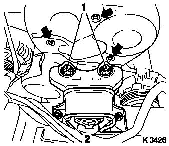
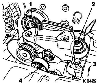
| 45. |
Remove alternator shackle (1)
| • |
Swing alternator backwards.
|
|
|
|
| 46. |
Reduce fuel pressure
Important: Observe safety
measures and national legislation.
|
| • |
With KM-J-34730-91
|
| • |
Unscrew test connection protective cap
|
|
|
|
| 47. |
Remove fuel line
| • |
From fuel distributor pipe
|
|
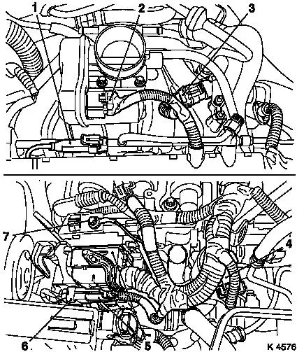
| 48. |
Remove wiring harness for engine management
| • |
Disconnect wiring harness plug
| – |
Throttle body module (2), knock sensor (1), intake pipe
pressure sensor (3), exhaust recirculation valve (4), engine
control unit (5), combination plug (6)
|
|
| • |
Remove ground cable (7)
|
|
|
|
| 49. |
Remove fuel distributor pipe
| • |
Remove 2 bolts (arrows)
|
| • |
Remove wiring harness for engine management together with
injectors
|
|
|
|
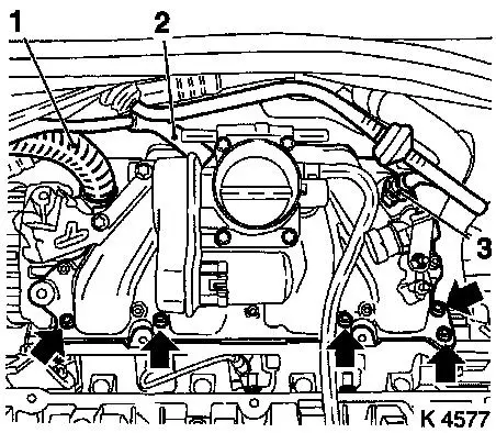
| 50. |
Remove intake manifold
| • |
Remove brake servo vacuum line (3)
|
| • |
Unclip wiring harness (1)
|
| • |
Remove tank vent valve line (2)
|
| • |
Remove 5 bolts (arrows)
|
|
|
|
| 51. |
Remove upper radiator hose
|
| 53. |
Remove engine vent flange
| • |
From engine control unit bracket
|
|
|
|
| 54. |
Remove heated oxygen sensor for mixture regulation
|
|
|
| 55. |
Remove exhaust manifold heat shield
|
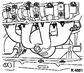
| 56. |
Remove exhaust manifold
|
|
|
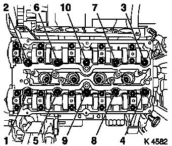
| 57. |
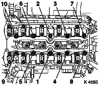
Remove cylinder head bolts
| • |
Remove 10 bolts
Note: Undo bolts in
order shown.
|
|
|
|
| 58. |
Remove cylinder head
Note: 2nd mechanic
required.
Important: Place cylinder head on
wooden blocks.
|
| • |
Remove cylinder head gasket
|
|
| 60. |
Remove con-rod bearing cap
Note: Observe cylinder
order.
| • |
Mark con-rods with con-rod bearing caps
|
Important: The mating surfaces of
the cod-rods and con-rod bearing caps form an individual fit and
must not be damaged or interchanged. Do not lay on mating
surfaces.
|
| • |
Push piston with con-rod upwards
|
|
|
|
| 65. |
Remove con-rod bearing cap
Note: Observe cylinder
order.
| • |
Mark con-rods with con-rod bearing caps
|
Important: The mating surfaces of
the cod-rods and con-rod bearing caps form an individual fit and
must not be damaged or interchanged. Do not lay on mating
surfaces.
|
| • |
Push piston with con-rod upwards
|
|
| 68. |
Remove con-rod bearing shells
| • |
Mark con-rod bearing shells
Note: Observe
order.
|
|
| 70. |
Insert con-rod bearing shells
| • |
In con-rod, con-rod bearing cap
|
|
| 71. |
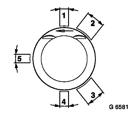
Adjust piston ring gaps
| • |
Turn piston rings
| – |
Upper rings in position (1)
|
| – |
Middle rings in position (4)
|
|
| • |
Turn oil scraper ring
| – |
Intermediate ring in position (5)
|
| – |
Steel band rings in position (2) or (3)
|
|
|
|
|
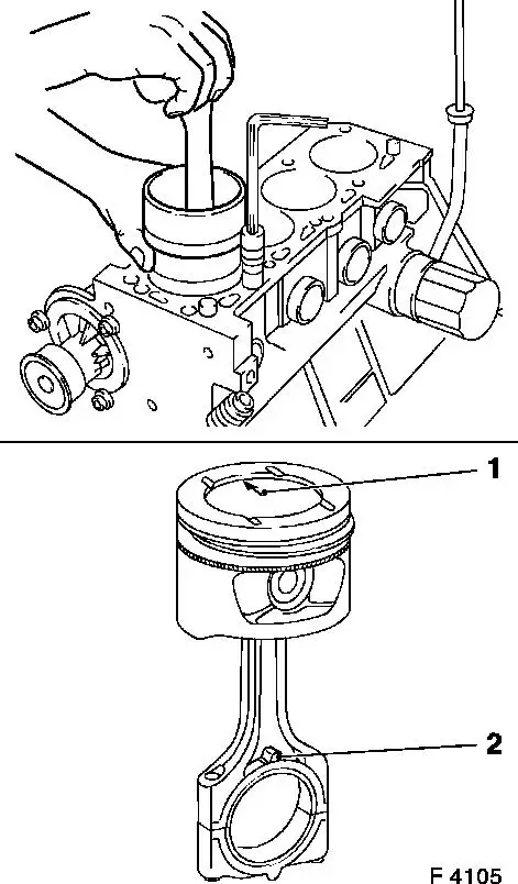
| 72. |
Install piston
| • |
Coat piston and cylinder bores with engine oil
|
Important: Arrow (1) on bottom of
piston points to engine timing side. Bead (2) on con-rod should
face transmission side
|
| • |
Compress piston rings with piston ring tensioner
|
|
|
|
| 74. |
Attach con-rod bearing cap
| • |
Coat con-rod journal with engine oil
|
Important: Bead on con-rod
bearing cap should face transmission side
|
| • |
Tighten bolts ( 25 Nm + 30°
)
|
|
| 75. |
Turn crankshaft
| • |
In direction of engine rotation by 180°
|
|
| 77. |
Install piston
| • |
Coat piston and cylinder bores with engine oil
|
Important: Arrow on bottom of
piston points to engine timing side. Bead on con-rod should face
transmission side
|
| • |
Compress piston rings with piston ring tensioner
|
|
| 79. |
Attach con-rod bearing cap
| • |
Coat con-rod journal with engine oil
|
Important: Bead on con-rod
bearing cap should face transmission side
|
| • |
Tighten bolts ( 25 Nm + 30°
)
|
|
| 81. |
Clean sealing surfaces
| • |
Cylinder block, crankshaft bearing bridge, oil pan, cylinder
head, timing case, exhaust manifold, oil filter housing, thermostat
housing, cylinder head cover
|
|
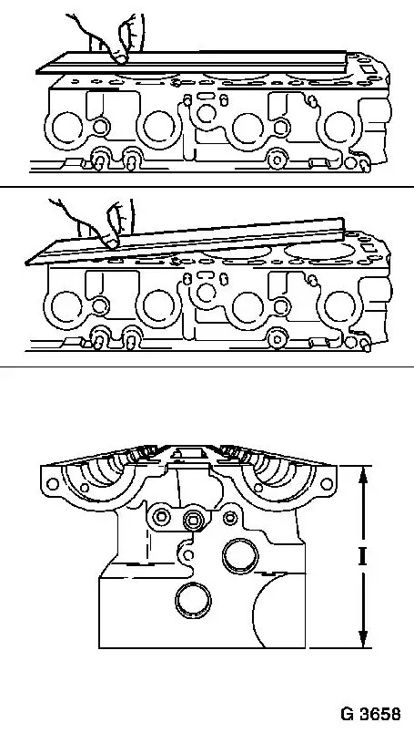
| 82. |
Check for plane surface
| • |
Cylinder head, cylinder block
|
| • |
With straightedge, feeler gauge
|
| • |
Measure cylinder head height
| – |
Sealing surface to sealing surface 134.90 - 135.10 mm (I)
|
|
|
|
|
| 83. |
Inspect components
| • |
Cylinder block, cylinder head, exhaust manifold, intake
manifold, cylinder head cover
|
|
| 84. |
Replace cylinder head gasket
| • |
Attach cylinder head gasket
Note: OBEN/TOP mark
must face upwards.
|
|
| 85. |
Attach cylinder head
Note: Second person
required
|
| 86. |
Fasten cylinder head
| • |
Replace cylinder head bolts
| – |
Screw in bolts by several threads
|
|
| • |
Tighten cylinder head bolts ( 25 Nm +
90°+ 90°+ 90° + 45° )
Note: Note tightening
sequence.
|
|
|
|
| 87. |
Attach exhaust manifold
|
| 88. |
Attach exhaust manifold heat shield
|
| 89. |
Install oxygen sensor, mixture regulation, heated
| • |
Apply special grease (black) to thread
|
| • |
using KM-6179 ( 30 Nm )
|
|
| 90. |
Install engine vent flange
|
| 92. |
Install intake manifold
|
| 93. |
Install fuel distributor pipe
|
| 94. |
Attach wiring harness for engine management
| • |
Clip in cable tie
| – |
With oil pressure switch and crankshaft sensor
|
|
|
| 95. |
Install upper radiator hose
|
| 96. |
Attach fuel line
| • |
Tighten union nut ( 15 Nm )
|
|
| 97. |
Install alternator shackle
|
| 98. |
Install rear toothed belt cover
|
| 99. |
Install toothed belt drive gear
| • |
Install crankshaft V-belt pulley bolt
|
|
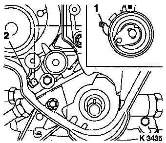
| 100. |
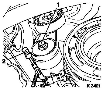
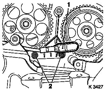
Install toothed belt tension roller
Important: Detent lever (1) of
toothed belt tension roller must engage in guide web (2) of oil
pump.
|
| • |
Bolt in bolt
Note: Adjust toothed
belt tension before tightening bolt.
|
|
|
|
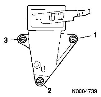
| 101. |
Install right engine bracket
| • |
Insert bolts with locking compound (red)
|
| • |
Tighten bolts ( 65 Nm + 45° -
60° )
Note: The rotating
angle to be applied must be set by eye.
|
| • |
Note tightening sequence (1 - 3).
|
|
|
|
| 102. |
Install intake side toothed belt guide roller
Important: The toothed belt guide
roller with the greater diameter is installed at the intake
side.
|
| • |
Tighten bolt 25 Nm
|
|
| 103. |
Install exhaust side toothed belt guide roller
|
| 104. |
Install camshaft sprockets
Note: Attach camshaft
sprocket with cylinder recognition to exhaust camshaft.
|
| 105. |
Fasten camshaft sprockets
Note: Second person
required
| • |
Tighten bolts ( 50 Nm + 60° +
15° )
| – |
Counterhold camshafts at hexagonal section
|
|
|
| 106. |
Fix camshaft sprockets in position.
Note: Marks must be
opposite one another and aligned with the top edge of the cylinder
head (I)
| • |
Use KM-852 (II)
| – |
Turn the camshafts at hexagonal section
|
|
|
| 107. |
Lock crankshaft
| • |
Set crankshaft to mark.
| – |
Turn crankshaft evenly
Note: Marks on drive
gear toothed belt and rear toothed belt cover must align (III).
|
|
|
|
|
| 108. |
Install toothed belt
Note: Pay attention to
direction of travel and timing marks.
| • |
Position toothed belt
Note: Tensioned side
must be taut (I).
|
|
|
|
| 109. |
Tension toothed belt
| • |
Tension toothed belt tension roller
| – |
Turn adjusting eccentric in direction of arrow (anticlockwise)
until pointer of the toothed belt tension roller is located just
before left stop
|
|
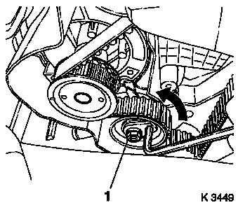
| • |
Fasten toothed belt tension roller bolt (1)
|
|
|
|
| 111. |
Timing, Check
| • |
Turn crankshaft (720°)
| – |
At crankshaft ribbed V-belt pulley bolt
Note: In direction of
engine rotation.
|
|
| • |
Set crankshaft to mark.
Note: Marks on drive
gear toothed belt and rear toothed belt cover must align (III).
|
| • |
Use KM-852 (II)
Note: Marks must be
opposite one another and aligned with the top edge of the cylinder
head (I)
|
|
|
|
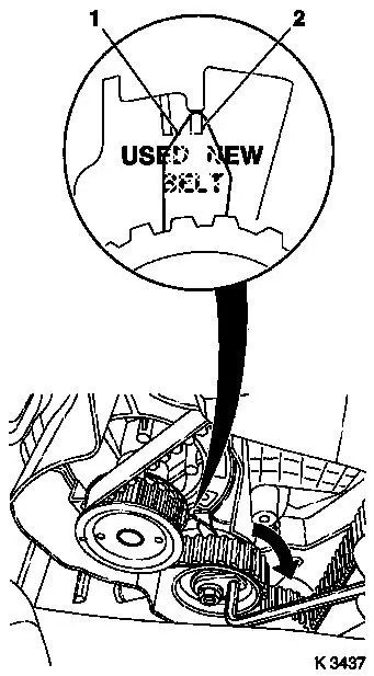
| 113. |
Adjust toothed belt tension
| • |
Release toothed belt tension roller
|
| • |
Turn adjustment eccentric in the direction of the arrow
(clockwise) until pointer (1) is aligned with the notch mark at the
toothed belt tension roller (2).
| – |
Adjust used toothed belts to the marking USED
|
| – |
Adjust new toothed belts to the marking NEW
|
|
| • |
Tighten toothed belt tension roller bolt 20 Nm
|
|
| 114. |
Check toothed belt tension
| • |
Turn crankshaft (720°)
Note: Pointers on the
toothed belt tension roller and notch mark must align.
| – |
Adjust used toothed belts to the marking USED
|
| – |
Adjust new toothed belts to the marking NEW
|
|
|
|
|
| 116. |
Attach camshaft sensor
| • |
Insert bolts with locking compound (red)
|
|
| 117. |
Install lower part of toothed belt cover
| • |
Clip to rear toothed belt cover
|
|
| 118. |
Install upper part of toothed belt cover
| • |
Clip to rear toothed belt cover
|
|
| 119. |
Connect wiring harness plug from camshaft sensor
| • |
Connect wiring harness plug from camshaft sensor.
|
|
| 120. |
Install right engine damping block
| • |
Fasten engine bracket adapter
| – |
Tighten bolts ( 60 Nm + 30° -
45° )
|
|
| • |
Fasten engine damping block
|
|
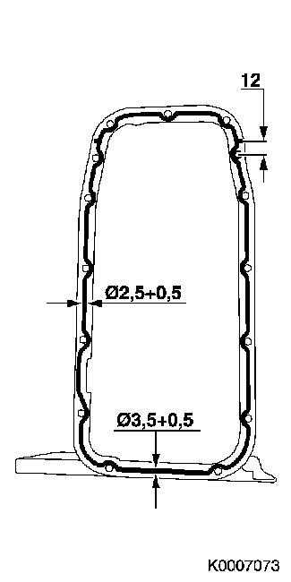
| 126. |
Install oil pan
Important: Complete installation
work within 10 minutes
|
| • |
Screw in bolts
|
| • |
Insert rear closure plug
|
|
|
|
| 127. |
Attach intake manifold support
|
| 128. |
Attach exhaust system
| • |
Attach oxygen sensor (catalytic converter control) cable to
intake manifold support and fold upwards
|
|
| 129. |
Install ribbed V-belt tensioner
| • |
Tension ribbed V-belt tensioner.
|
|
| 130. |
Attach crankshaft ribbed V-belt pulley
| • |
Tighten bolt 95 Nm + 30° +
15°
|
| • |
Insert front sealing plug
|
|
| 131. |
Install ribbed V-belt
Note: Note running
direction and installation position
| • |
Release ribbed V-belt tensioner
|
|
| 132. |
Install ribbed V-belt cover
|
| 134. |
Mount right front wheel.
|
| 136. |
Fasten right front wheel.
|
| 137. |
Install cylinder head cover
Important: Complete installation
work within 10 minutes
|
| • |
Tighten bolts 8 Nm
|
| • |
Attach engine vent hose
|
| • |
Connect cable harness plug of oxygen sensor, mixture
regulation, heated
|
|
|
|
| 138. |
Install catalytic converter control oxygen sensor wiring
harness plug
| • |
Connect wiring harness plug.
|
|
| 139. |
Install preheater hoses for throttle body module
| • |
Connect wiring harness plug for coolant temperature sensor
|
|
| 140. |
Attach brake servo vacuum line
|
| 141. |
Install ignition module
| • |
Connect wiring harness plug.
|
|
| 142. |
Install air cleaner housing
| • |
Install air intake hose.
|
| • |
Attach engine vent hose
|
| • |
Install air intake pipe
|
| • |
Clip in tank vent valve
|
| • |
Connect wiring harness plug.
|
|
| 143. |
Install engine cover.
| • |
Unscrew oil filler pipe cap
|
| • |
Screw on oil filler pipe cap
|
|
| 145. |
Calibrate steering angle sensor
| • |
Switch on ignition
Note: Rotate the
steering wheel one time from its right-hand to its left-hand
stop.
|
|
| 146. |
Pour in engine oil and coolant
| • |
Note prescribed quantities of engine oil and coolant
|
| • |
Start engine and allow to run until oil pressure telltale
extinguishes.
|
| • |
Check engine oil level, if necessary correct.
Note: Top up and bleed
cooling system – see operation "Cooling System, Top Up and
Bleed".
|
|
| 147. |
Reset service interval using TECH 2
Note: If the customer
chooses ECOService, connect TECH 2 and reprogram the engine control
unit. Reset the service interval using TECH 2 - see operation
"Engine oil change".
|
| 148. |
Fill out the service sticker
Note: Fill out the
service sticker - see operation "Flexible maintenance
intervals"
|
| 149. |
Program volatile memories
|
|