|
Relay Frame – Engine Compartment Main Fuse
Carrier, Remove and Install
 Remove Remove
| 3. |
Remove relay frame engine compartment fan module 
|
| 4. |
Remove relay box Body Control Module
| • |
Release relay box, Body Control Module
|
|
|
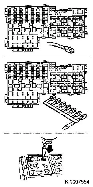
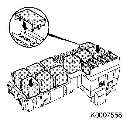
| 5. |
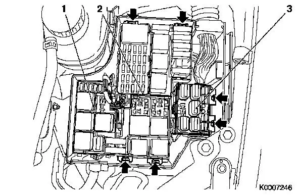
Unclip relay frame for engine compartment main fuse carrier (2)
and relay frame for engine compartment light module (3)
(arrows)
|
|
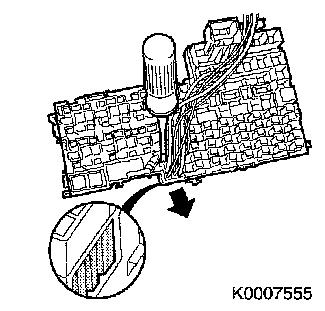
| 6. |
Release necessary wiring harnesses, disconnect necessary wiring
harness plugs and unscrew necessary earth connections
|
| 7. |
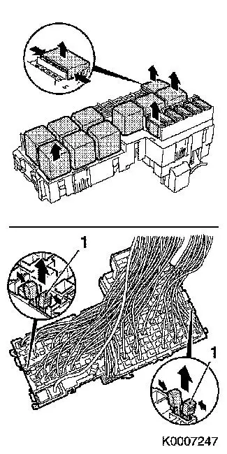
Pull out cover flap, relays and fuses.
|
| 8. |
Remove cable ties (tape loops) on the back
Note: Note the
installation positions of the relays and fuses.
|
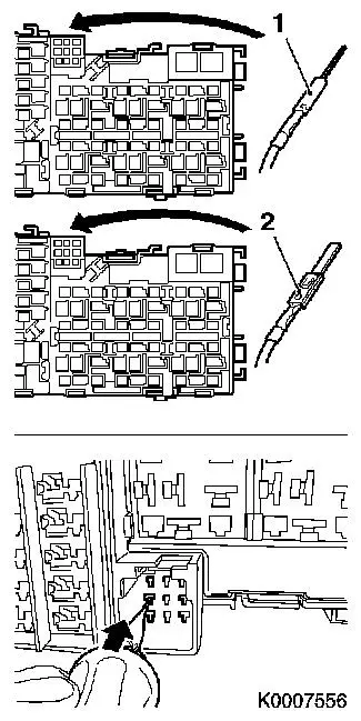
| 9. |
Compress head of housing retainers (1) and remove
|
|
|
| 10. |
Release secondary retainer:
|
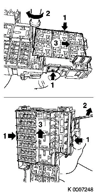
| 11. |
Release both housing parts on both sides (1)
|
| 12. |
Lever up both housing parts (2) and in both cases slide in
direction (3)
Note: For a clearer
illustration, the cables are not shown.
|
|
|
| 13. |
The individual cables must be replaced in the new housing one
by one if possible. If this is not possible, the cables must be
marked correspondingly.
Note: With the new
housings, the secondary retainer must be released.
|
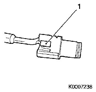
| 14. |
Before inserting into the new housing, the spring contacts must
be checked. If necessary, the lock (1) must be corrected
carefully.
|
|
|
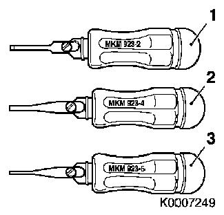
| 15. |
Release tools required:
| 1. |
MKM-923-2 |
| 2. |
MKM-923-4 |
| 3. |
MKM-923-5 |
| 4. |
2 hex screwdriver 2 mm (not shown) or suitable
tool |
|
|
|
|
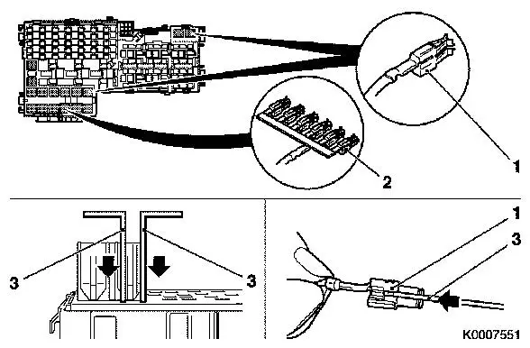
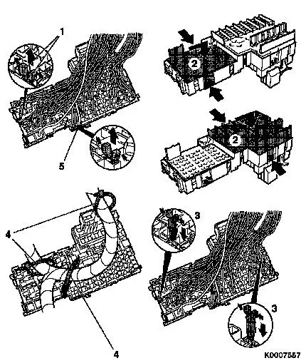
| 16. |
Release locks of the Maxi-Power-Timer contacts (1) and
Maxi-Power-Timer current conductors (2) with two 2 mm hex
screwdrivers (3) and pull out.
Note: The two locks are
on the sides on the contacts.
Note: Only one side is
depicted in the lower part of the illustration.
|
|
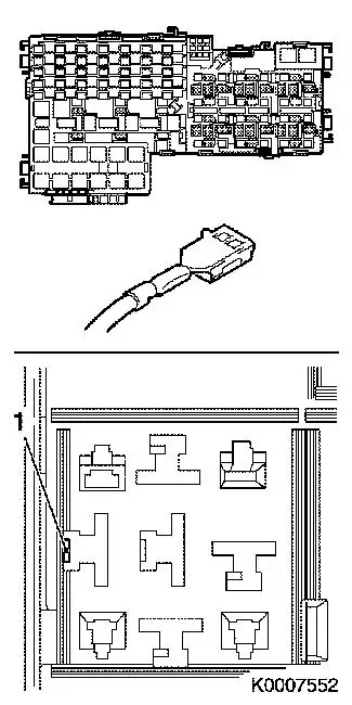
| 17. |
Release locking mechanism of the RT 6.3–contacts with
Special Tool MKM-923-2 and pull out the
contacts
Note: The locks (1) for
these contacts are in the housing.
|
|
|
| 18. |
Release locking mechanisms of the Fasten 9.5-contacts with
Special Tool MKM-923-2 and pull out the
contacts
Note: The locks (1) are
on the contacts.
|
|
|
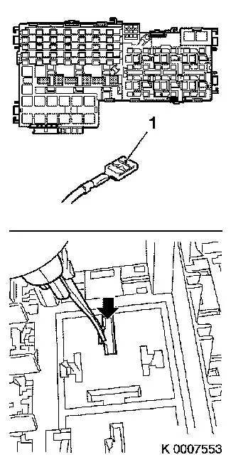
| 19. |
Release locking mechanisms of the MP 2.8-contacts and the MP
2.8 current conductor with Special Tool MKM-923-4 and pull out the contacts and the current
conductors.
Note: The locks are on
the contacts.
|
|
|
| 20. |
Move the secondary locking mechanism (9-pin drawer) with a
suitable aid from the limit position to the preliminary position
(approx. 1mm)
|
| 21. |
The preliminary position is reached when the secondary locking
mechanism is aligned with the housing wall of the lower part. In
the illustration, the secondary locking mechanism is still in the
locked position.
|
|
|
| 22. |
Release the locking mechanisms of the Ducon 1.5-contacts (1)
and Ducon 2.8 contacts (2) with Special Tool MKM-923-4 and pull out the contacts
|
|
|
 Install
| 23. |
Insert the contacts that have not yet been inserted into the
previously noted chamber of the new housing
|
| 24. |
Lock the secondary locking mechanism( 5) (9–pin drawer)
(push in to the stop)
|
| 25. |
Compress head of the two housing retainers (1) and remove
|
| 26. |
Release secondary locking mechanisms (2) and slide the upper
parts into the limit position. Upper and lower parts are now
flush
|
| 27. |
Secure upper parts by inserting the housing retainers (3)
|
| 28. |
Check correct seating of all the contacts
|
| 29. |
Secure cables at 3 points (4) with tape loops
|
|
|
|
| 30. |
Insert relays, fuses and cover flap
|
| 31. |
Secure released wiring harnesses, connect disconnected wiring
harness plugs, connect released earth connections
|
|
| 32. |
Install relay box of body control module
|
| 33. |
Insert relay frame for engine compartment main fuse carrier
into relay box
|
| 34. |
Install relay carrier, engine compartment fan module
|
| 37. |
Program volatile memories
|
| 38. |
Electrical function check
|
|
