|
Windscreen, remove and install or replace
Note: This document
describes the procedure for removing the glass from the windscreen
using the glass removal system BO-46974 .
As a supplement to the existing video VT 54, individual steps will
be shown for removing the windscreen glass without destroying
it.
Remove glass from windscreen
Warning: Before
starting work, put on the gloves and protective goggles contained
in tool kit BO-46974 to prevent injuries
to the eyes and hands.
Tool BO-46974 is recommended for
removing glass without destroying it. Further information can be
found in video VT 54.
Note: Position the
vehicle on level ground and move the front wheels to the
straight-ahead position
 Remove Remove
|
| 4. |
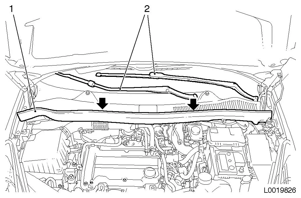
Remove wind protection panel (1) seal
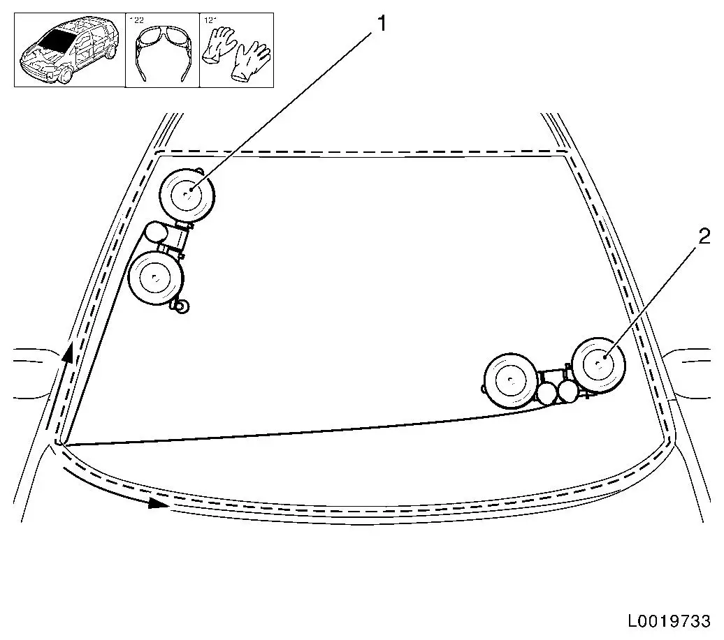
|
| 5. |
Remove wiper arms (2)
| • |
Pull 2x wiper arms off shaft with KM-6626-20
|
|
| 6. |
Remove wind protection panel
| • |
Unscrew 2x bolt (arrows)
|
| • |
Remove wind protection panel from windscreen guide
|
| • |
Separate washer system hose
|
|
|
| 8. |
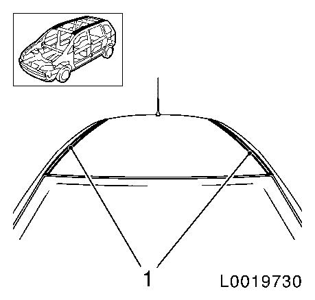
Detach roof trim strip (1) in front area on both sides
|
|
|
|
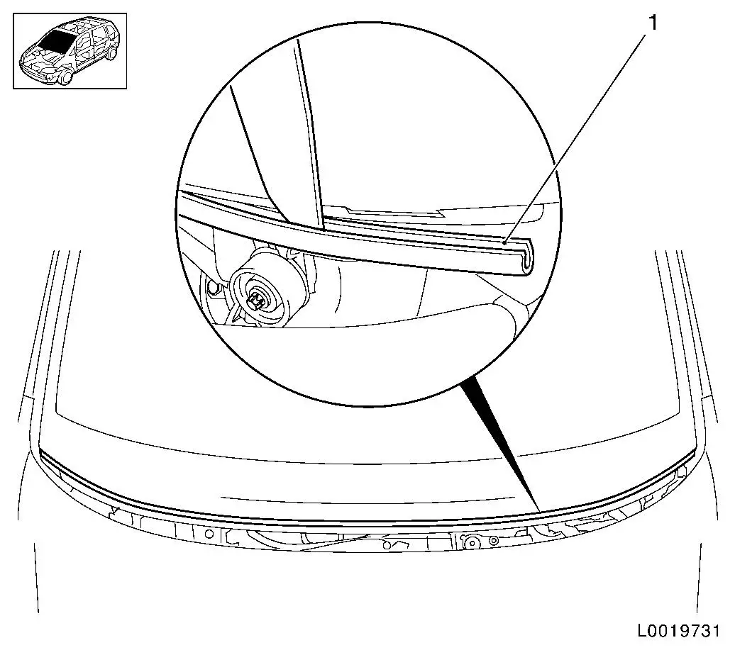
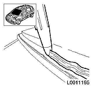
| 9. |
Remove lower windscreen trim strip (1)
|
|
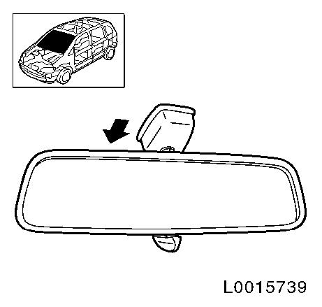
| 10. |
Detach inside rear view mirror
| • |
Manual interior rear view mirror 
|
| • |
Electric interior rear view mirror
|
|
|
|
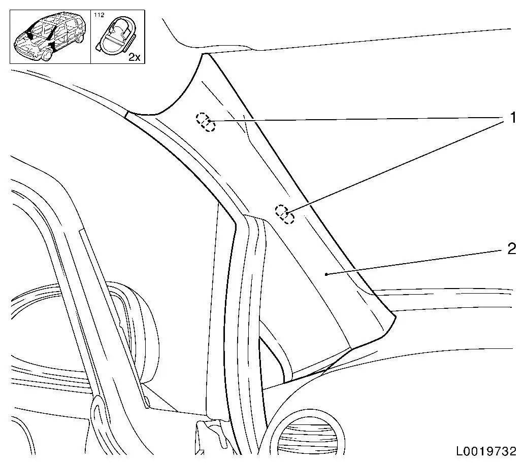
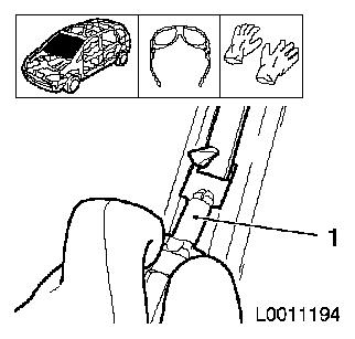
| 11. |
Remove A-pillar panelling (2) - both sides
| • |
Remove A-pillar panelling from guide
|
|
|
|
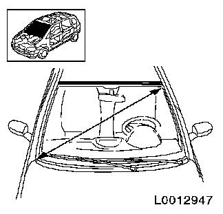
| 12. |
Measure diagonals of front screen
| • |
Cut off cutting wire to four times the required length, 6000
mm
Note: The circumference
of the roll of wire is approx. 1 metre.
|
|
|
|
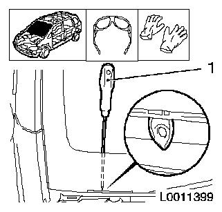
| 13. |
Heat the awl using a suitable tool
|
| 14. |
Push awl (1) out through adhesive bed in bulkhead area
Note: To protect the
instrument panel padding, place suitable material between
windscreen and instrument panel padding. Ensure that the windscreen
is not damaged else stress cracks can occur in the windscreen.
|
|
|
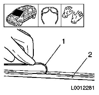
| 15. |
Lay wire below windscreen all round.
Note: At the
windscreen, the cutting wire (1) must be rolled under the rubber
seal (2) all round. Use soap as an aid.
|
|
|
| 16. |
Pull through wire
| • |
Thread both ends of the cutting wire into the hole of the awl
and bend up
|
| • |
Pull cutting wire into the interior to the centre of the
steering wheel using an awl
|
|
| 17. |
Position seat
| • |
Position seats so that the complete windscreen can be reached
with the lifting winch
|
|
|
| 18. |
Position winches in the vehicle
| • |
Position the winch with one winding head (1) on the right-hand
side of the windscreen
|
| • |
Position the winch with two winding heads (2) in the lower
left-hand area of the windscreen
|
| • |
Attach 2x cutting wire to winch
Note: Check that the
cutting wire is laid correctly at the winch deflection roller
| – |
Insert transfer ratchet and pre-tension cutting wire
|
|
|
| 19. |
Cut out windscreen
| • |
Use plastic plate to protect instrument panel padding
| – |
Cut out the windscreen using the winch and two winding heads
until the cutting wire is level with the winding head
|
| – |
Arrow shows the path taken by the cutting wire
|
|
|
| 20. |
Cut out windscreen
| • |
Use retainers to protect the A-pillar
Note: Increased tension
is required to cut in the area of the A-pillar/bulkhead.
|
| • |
Cut out the windscreen using the winch and one winding head
until the cutting wire is level with the winding head
|
| • |
Arrow shows the path taken by the cutting wire
|
|
|
|
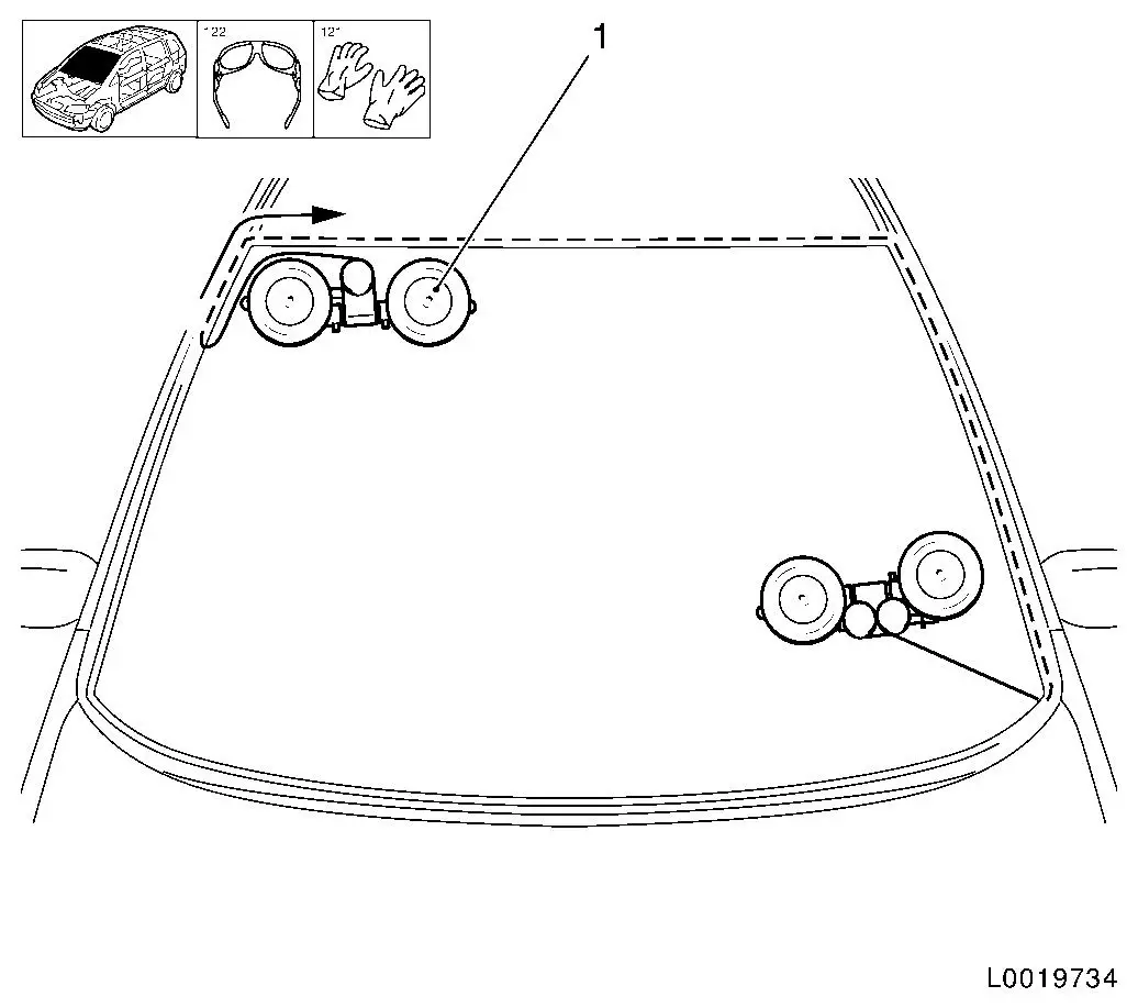
| 21. |
Position winch with one winding head (1) in the vehicle
| • |
Attach roof frame in the top right-hand area
|
| • |
Insert transfer ratchet and pre-tension cutting wire
Note: Check that the
cutting wire is laid correctly at the winch deflection roller
|
|
| 22. |
Cut out windscreen
| • |
Cut out the windscreen using the winch and one winding head
until the cutting wire is level with the winding head
Note: Use lubricant on
the deflection roller; increased tension is required to cut in the
area of the windscreen radius, avoid damage to moulded headlining
with plastic sheets.
|
| • |
Arrow shows the path taken by the cutting wire
|
|
|
|
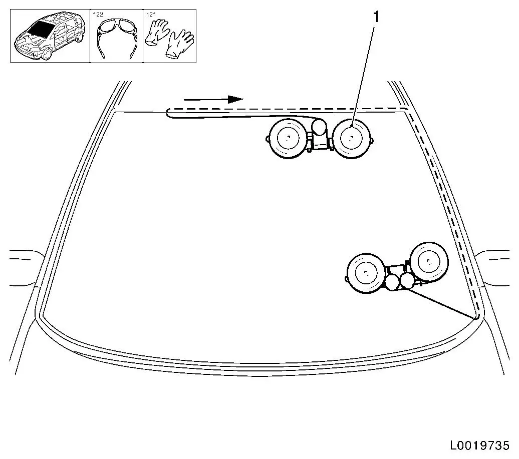
| 23. |
Position winch with one winding head (1) in the vehicle
| • |
Attach roof frame in the left area
|
| • |
Insert transfer ratchet and pre-tension cutting wire
Note: Check that the
cutting wire is laid correctly at the winch deflection roller
|
|
| 24. |
Cut out windscreen
| • |
Cut out the windscreen using the winch and one winding head
until the cutting wire is level with the winding head
Note: Avoid damage to
moulded headlining with plastic sheet
|
| • |
Arrow shows the path taken by the cutting wire
|
|
|
|
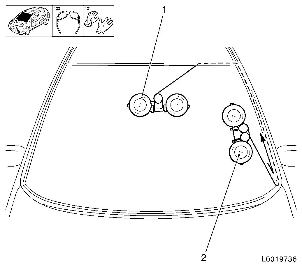
| 25. |
Position winch with one winding head (1) in the vehicle
| • |
Attach in the centre area of the windscreen
|
| • |
Insert transfer ratchet and pre-tension cutting wire
Note: Check that the
cutting wire is laid correctly at the winch deflection roller
|
|
| 26. |
Position winch with two winding heads (2) in the vehicle
| • |
Attach in the lower left area of the A-pillar
|
| • |
Insert transfer ratchet and pre-tension cutting wire
Note: Check that the
cutting wire is laid correctly at the winch deflection roller
|
|
| 27. |
Cut out windscreen
| • |
Cut out the windscreen using the winch and two winding heads
until the cutting wire is level with the winding head
Note: Use a lubricant
on the deflection roller, more pulling force is required to cut in
the windscreen corner area.
|
| • |
Arrow shows the path taken by the cutting wire
|
|
|
|
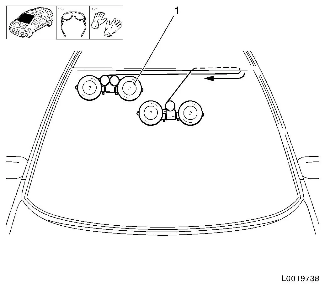
| 28. |
Position winch with two winding heads (1) in the vehicle
| • |
Attach roof frame in the left area
|
| • |
Insert transfer ratchet and pre-tension cutting wire
Note: Check that the
cutting wire is laid correctly at the winch deflection roller
|
|
| 29. |
Cut out windscreen
| • |
Cut out the windscreen until the cutting wire is level with the
winch
Note: Use lubricant on
the deflection roller; increased tension is required to cut in the
area of the windscreen radius, avoid damage to moulded headlining
with plastic sheets.
|
| • |
Arrow shows the path taken by the cutting wire
|
|
|
|
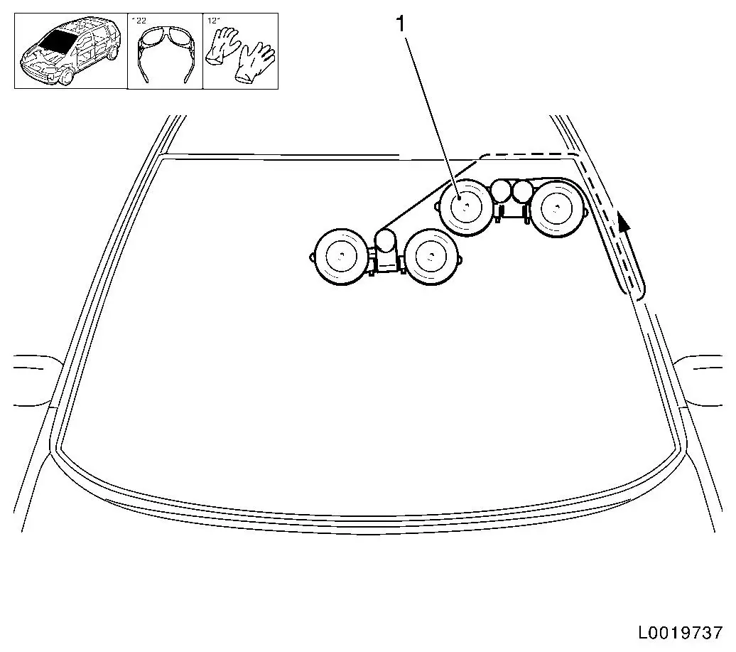
| 30. |
Position winch with two winding heads (1) in the vehicle
| • |
Attach roof frame in the right-hand area
|
| • |
Insert transfer ratchet and pre-tension cutting wire
Note: Check that the
cutting wire is laid correctly at the winch deflection roller
|
|
| 31. |
Cut out windscreen
| • |
Cut out the windscreen until the cutting wire has cut through
the adhesive bead completely
Note: Avoid damage to
moulded headlining with plastic sheet
|
| • |
Arrow shows the path taken by the cutting wire
|
|
|
| 32. |
Remove both cutting tools
|
| 34. |
Remove windscreen
Note: 2nd mechanic
required.
|
| 35. |
Cut adhesive bead on the vehicle
| • |
Cut the adhesive bead all round using the knife supplied (1) to
around 1 mm thickness
|
|
|
|
| 36. |
Repair any paint damage
| • |
Using a touch-up pen to match the colour of the vehicle, repair
any paint damage
|
|
| 37. |
Cut adhesive bead on the glass
| • |
Cut the adhesive bead all round using the knife supplied to
around 1 mm thickness
|
|
 Install
| 38. |
Apply primer
Note: Only with new
glass pane
|
| 39. |
Apply adhesive bead
| • |
Cut into the tip of the cartridge in such a way that a bead of
adhesive approx. 13 mm thick is
produced
|
|
|
|
| 40. |
Insert windscreen
| • |
Insert windscreen with MKM-641
|
| • |
Position using fibre tape
|
|
| 42. |
Observe lay-over time
|
| 43. |
Attach roof trim strip - both sides
|
| 44. |
Attach interior rear view mirror
| • |
Manual interior rear view mirror
|
| • |
Electric interior rear view mirror
|
|
| 45. |
Fit A-pillar panelling - both sides
| • |
Insert A-pillar panelling in guide
|
| • |
Clip in 2x clips
Note: Ensure door
rubber strip sits correctly
|
|
| 47. |
Install lower windscreen trim strip
|
| 48. |
Insert wind protection panel
| • |
Connect screen washer system hose at separating point
|
| • |
Position wind protection panel and clip into windscreen holder
strip guide at bottom
|
|
| 49. |
Fit sealing strip for wind protection panel
|
| 50. |
Install wiper arm - both sides
|
| 53. |
Program volatile memories
|
|
