|
Brake Servo, Replace (LHD)
 Remove Remove
| 3. |
Release and separate wiring harness plug (3) for hydraulic
modulator
|
| 4. |
Release 2x brake line (1) from brake master cylinder
| • |
Unscrew 2x union nut (5)
|
|
| 5. |
Detach 2x brake line from brake master cylinder (1) to
hydraulic modulator
| • |
Unscrew 2x union nut (2)
|
|
| 6. |
Detach 4x brake line from hydraulic modulator
| • |
Unscrew 4x union nut (4)
|
|
|

|
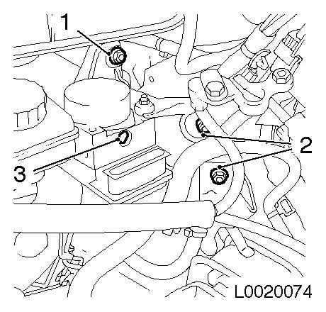
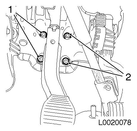
| 7. |
Remove hydraulic modulator with bracket
| • |
Unscrew 3x nut (1), (2)
|
| • |
Remove hydraulic modulator (3) with bracket
|
|
|
|
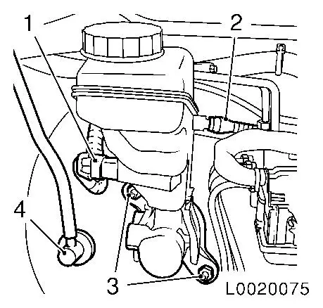
Important: Remove brake master
cylinder horizontally, pressure piston can fall out.
|
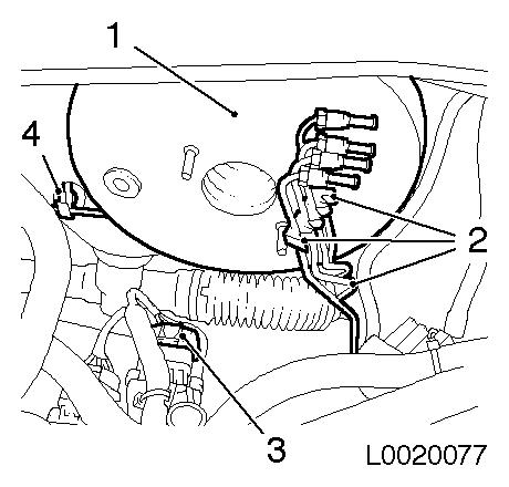
| 8. |
Remove brake master cylinder with brake fluid reservoir
| • |
Release and separate wiring harness plug (1) for brake fluid
level
|
| • |
Unscrew 2x nut (2)
Note: Check for
leaks!
|
|
| 9. |
Detach vacuum line (3) from brake servo
|
|
|
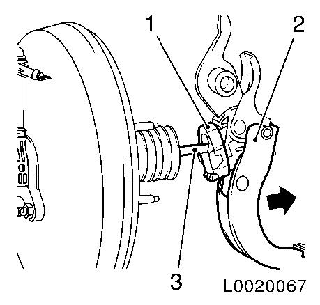
| 10. |
Detach brake pedal (2) from piston rod (3) of brake servo
Note: 2nd person
required. Pull brake brake pedal during dismantling. After removal,
clip (1) must always be replaced.
|
|
|
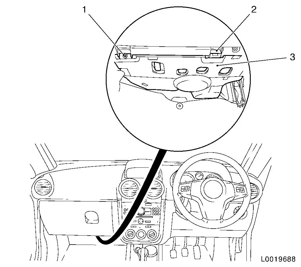
| 11. |
For diesel engines: Remove footwell panelling (3), lower,
driver's side
| • |
Unclip panelling (3) (2) and remove
|
|
|
|
| 12. |
Remove air duct (1), driver's side footwell
| • |
Remove expanding rivet (2)
|
|
|
|
| 13. |
Lock steering in straight ahead position
|
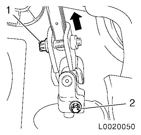
| 14. |
Detach steering intermediate spindle from steering gear
| • |
Unscrew 2x bolt (1), (2)
|
| • |
Push up joint (arrow) and pull steering spindle from steering
gear
|
|
|
|
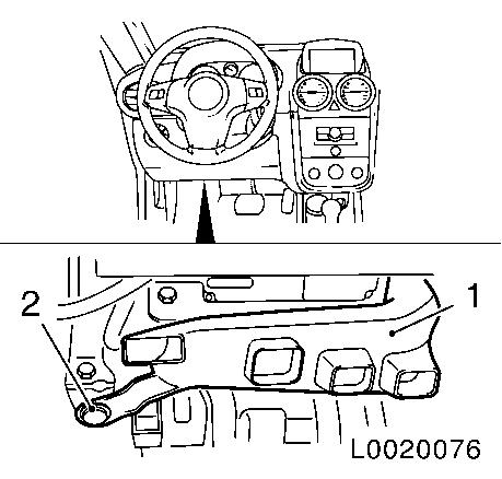
| 15. |
Detach brake servo
| • |
Unscrew 4x nut (1), (2)
|
|
|
|
| 16. |
Unclip brake lines from bracket (2), (4)
|
| 17. |
Release and separate wiring harness plug (3) for switch
module
|
| 18. |
Remove brake servo (1)
|
|
|
 Install
| 19. |
Insert brake servo
Note: When inserting,
ensure that piston rod of brake servo is seated correctly in brake
pedal.
|
| 20. |
Clip brake lines into bracket
|
| 21. |
Connect and lock wiring harness plug for switch module
|
| 23. |
Attach brake pedal to piston rod
|
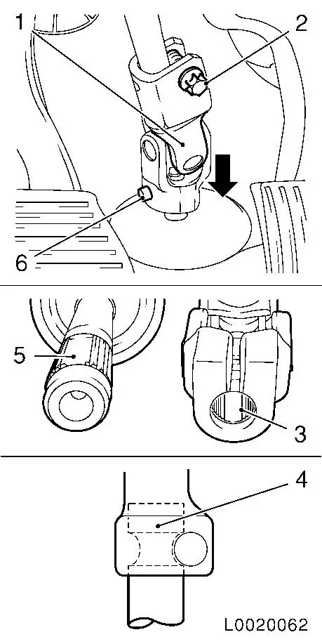
| 24. |
Attach lower universal joint (1)
| • |
Push onto steering spindle (arrow)
Note: The recess (3) in
the fine toothing in the lower universal joint must align precisely
with the recess (5) in the fine toothing on the steering pinion.
The bore in lower universal joint (1) must align with the groove on
the steering pinion (4).
|
| • |
Fit bolt (6) with locking compound and tighten 55 Nm
|
| • |
Fit bolt (2) with locking compound and tighten 40 Nm
|
|
|
|
| 25. |
Install air guide, driver's side footwell
|
| 26. |
For diesel engines: Install footwell panelling lower, driver's
side
|
| 27. |
Install hydraulic modulator with bracket
|
| 28. |
Detach 4x brake line from hydraulic modulator
| • |
Tighten 4x union nut 16 Nm
|
|
| 29. |
Attach 2x brake line from brake master cylinder to hydraulic
modulator
| • |
Tighten 2x union nut 16 Nm
|
|
| 30. |
Attach brake master cylinder with brake fluid reservoir to
brake servo
Note: Use new
gasket
| • |
Clip in wiring harness for brake fluid level 2x
|
| • |
Fix wiring harness plug
|
|
| 31. |
Attach 2x brake line to brake master cylinder
| • |
Tighten 2x union nut 16 Nm
|
|
| 32. |
Attach vacuum line brake servo
|
| 33. |
Connect and lock wiring harness plug for ABS control unit
|
| 34. |
Install battery holder
|
| 35. |
Remove MKM-558-10 from brake fluid
reservoir
|
| 36. |
Program volatile memories
|
| 37. |
Bleed brake system and check for leaks 
|
|
