|
Engine maintenance using a section engine
Warning: When
working on the Common Rail system, wait for one minute after
switching off the engine. The system reduces the pressure
automatically.
Important: When
working on the fuel system, pay strict attention to cleanliness as
even the smallest particle of dirt may lead to malfunctions in
engine operation or the fuel system. Seal opened fuel connections
with suitable closure plugs 1) .
Closure plugs are intended for single use.
 Remove Remove
| 2. |
Detach transmission from engine
- For transmission F17-5 and M20-6

- For manual transmission M20-6 MTA
|
| 3. |
Detach starter
| • |
Detach 2x wiring harness
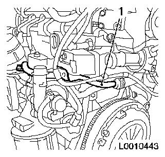
|
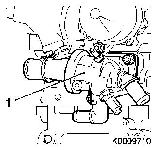
|
|
|
| 4. |
Remove thrust plate with clutch disc
|
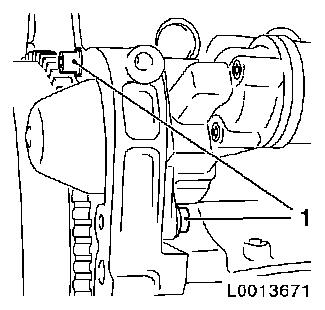
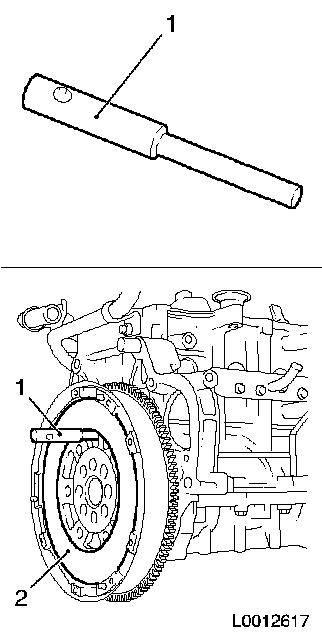
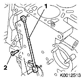
| 5. |
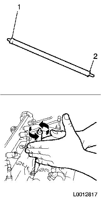
Lock crankshaft
| • |
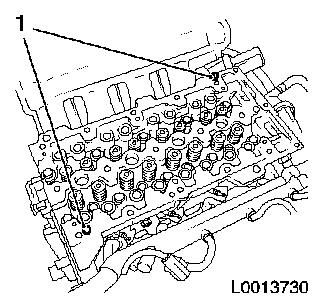
Insert EN-46778 (1) through flywheel
(2) into cylinder block
|
|
|
|
| 6. |
Place collecting pan underneath.
|
| 7. |
Drain engine oil
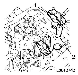
| • |
Tighten drain bolt 20 Nm
|
|
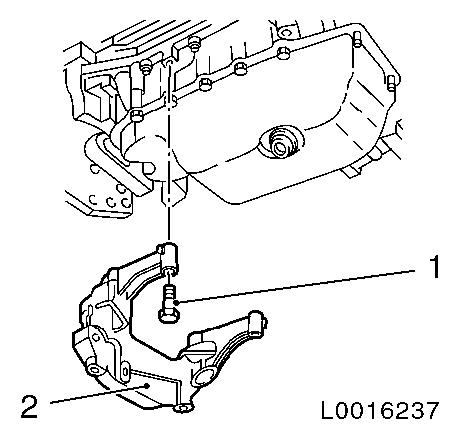
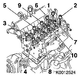
| 9. |
Remove transmission bracket (2)
| • |
Detach from cylinder block base plate
| – |
Unscrew 4x bolts (1)
Note: Note different
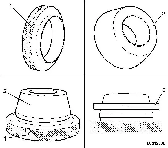
bolt lengths!
|
|
|
|
|
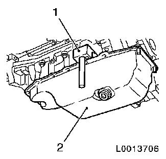
| 10. |
Remove oil pan (2)
| • |
Unscrew 2x nuts
Note: Carefully detach
oil pan (2) from cylinder block base plate using KM-J-37228 (1).
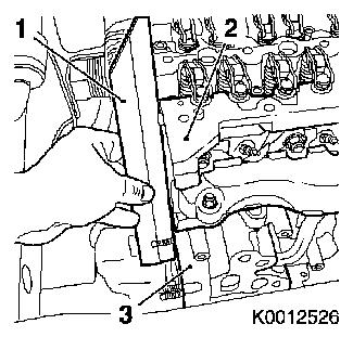
|
|
|
|
| 12. |
Detach engine wiring harness on intake side
| • |
Disconnect 4x injector wiring harness plug
|
| • |
Disconnect 4x glow plug wiring harness plug
|
| • |
Disconnect wiring harness plug for camshaft sensor
|
| • |
Disconnect wiring harness plug of crankshaft sensor
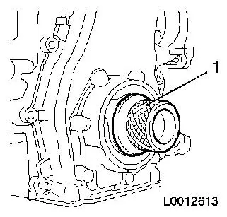
|
| • |
Disconnect wiring harness plug for coolant temperature
sensor
|
|
| 13. |
Disconnect engine wiring harness on exhaust side
| • |
Disconnect wiring harness plug of rail pressure sensor
|
| • |
Disconnect wiring harness plug of boost pressure sensor
|
| • |
Disconnect wiring harness plug of rail pressure regulator
|
| • |
Disconnect wiring harness plug of EGR valve
|
|
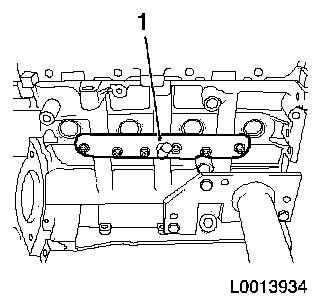
| 14. |
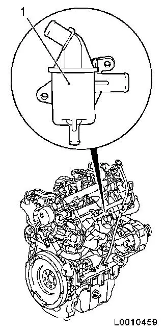
Detach engine wiring harness
|
| 15. |
Place collecting pan underneath.
|
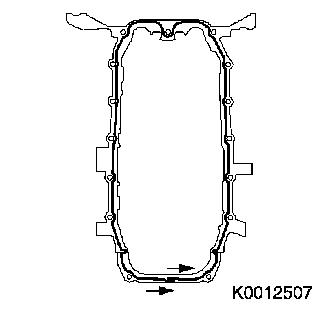
Important: After detaching the
pressure lines, seal the openings of the injectors, the
high-pressure pump and the accumulator using protective caps
(select suitable protective caps from the spare parts
catalogue).
|
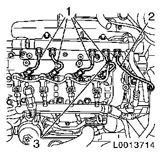
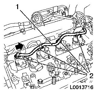
| 16. |
Detach high pressure lines
| • |
Detach 4x high pressure line (1) from accumulator to
injector
|
| • |
Remove high pressure line (2) from high pressure pump to
accumulator
|
| • |
Unclip oil leak line (3)
|
|
|
|
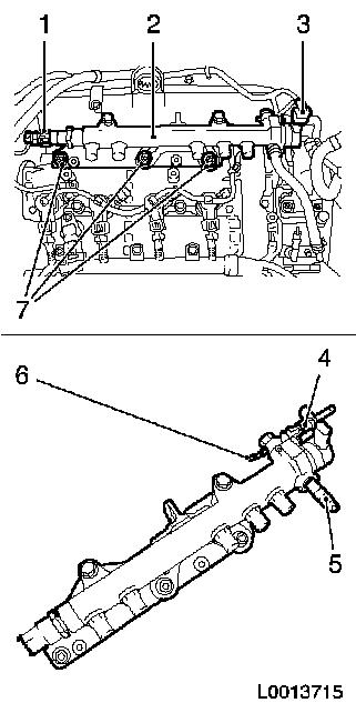
| 17. |
Remove accumulator (2) with accumulator bracket
| • |
Disconnect 2x wiring harness plug (1) and (3)
|
| • |
Deatch fuel return line (high pressure to accumulator) from
connection (5)
|
| • |
Detach oil leak line from connection (6)
|
| • |
Unscrew 3x bolts (7)
Note: Remove engine
transport tab.
|
| • |
Detach fuel return line from connection (4)
| – |
Undo quick-release fitting with KM-796-A
|
|
|
|
|
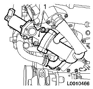
| 18. |
Deatch EGR valve (1) with EGR cooler
| • |
Detach EGR pipe from intake manifold
|
| • |
Detach coolant hose from thermostat housing
|
|
|
|
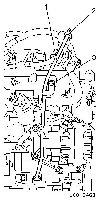
| 19. |
Detach oil dipstick guide tube (1) with oil dipstick (2)
|
|
|
| 20. |
Detach oil separator (1) for engine ventilation
| • |
Detach engine vent hose from timing case
|
| • |
Detach engine vent hose from flange
|
|
|
|
| 21. |
Detach exhaust port for cylinder block ventilation (1)
|
|
|
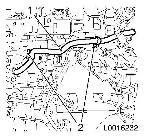
| 22. |
Detach coolant feed pipe (1)
| • |
Detach from heat exchanger
|
| • |
Detach from cylinder block
|
| • |
Unclip 2x wiring harness bracket
|
|
|
|
| 23. |
Detach thermostat housing (1) from cylinder head
|
|
|
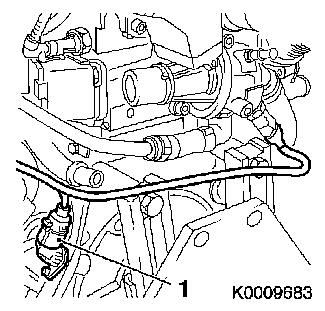
| 24. |
Remove coolant pipe (1)
|
|
|
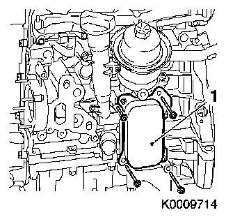
| 25. |
Detach oil filter housing (1)
|
|
|
| 26. |
Remove crankshaft sensor (1)
|
|
|
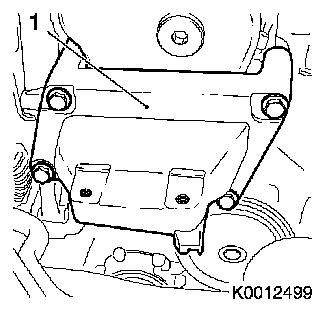
| 27. |
Remove right engine damping block adapter (1)
|
|
|
| 28. |
Remove ribbed V-belt tensioner
|
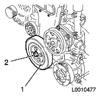
| 29. |
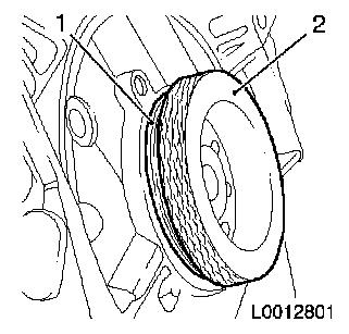
Remove torsional vibration damper (1)
| • |
Unscrew 4x bolts
Note: Counterhold
against bolt, torsional vibration damper flange (2).
|
|
|
|
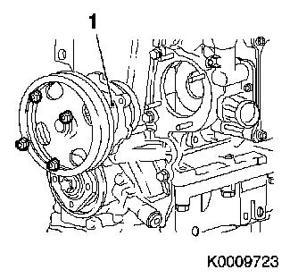
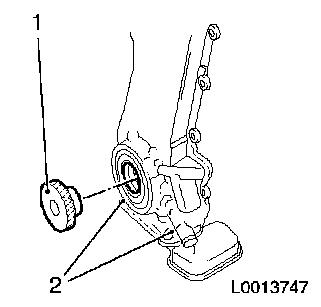
| 30. |
Remove coolant pump (1)
|
|
|
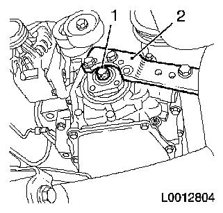
| 31. |
Detach torsional vibration damper flange
Note: Left-handed
thread
| • |
Unscrew bolt (1)
| – |
Counterhold with KM-662-C (2)
|
|
|
|
|
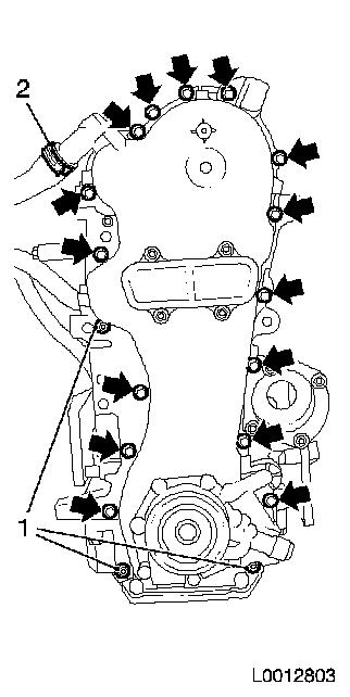
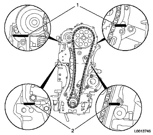
| 32. |
Remove timing case
| • |
Detach engine vent hose (2) from timing case
|
| • |
Unscrew 15x bolts (arrows)
|
|
|
|
| 33. |
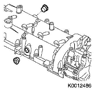
Remove 2x closure bolt from camshaft housing
|
|
|
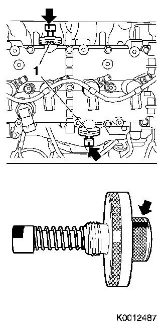
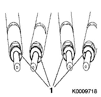
| 35. |
Lock camshafts
| • |
Screw in 2x camshaft reference drift EN-46781 (1)
|
| • |
Ensure correct installation position
Note: Fixing for
reference drift must be installed in the horizontal position. To do
this, apply marking to reference drift as an aid (arrows).
|
| • |
Turn camshafts at camshaft drive gear bolt back and forth until
EN-46781 engages in both camshafts
|
|
|
|
| 36. |
Detach timing chain tensioner
| • |
Apply tension to chain tensioner, lock in pre-tensioned
position with KM-955
|
|
|
|
| 37. |
Detach timing chain tension rail
|
| 38. |
Remove timing chain sliding rail
|
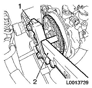
| 39. |
Slacken camshaft drive gear
| • |
Counterhold with KM-6347 (1) and
KM-956-1 (2) on camshaft drive gear
|
|
|
|
| 40. |
Remove timing chain with camshaft drive gear and crankshaft
drive gear
|
| 41. |
Detach timing chain oil spray nozzle (1)
|
|
|
| 42. |
Remove oil leak line (1)
| • |
Release 4x clamp (2) in direction of arrow
|
|
|
|
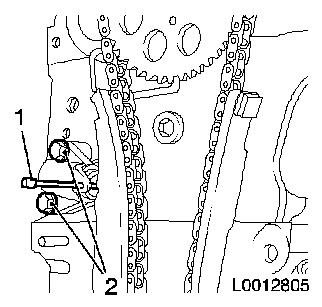
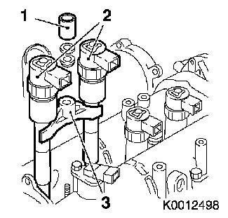
| 43. |
Remove injectors
| • |
Detach 2x injector bracket (3)
| – |
Unscrew 2x nuts (1)
Note: Injectors (2) can
only be removed in pairs (cylinder 1 and 2 or 3 and 4) with
bracket.
|
|
|
|
|
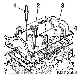
| 44. |
Detach camshaft housing (3)
| • |
Unscrew 16x bolt (2)
Note: Note different
bolt lengths!
|
| • |
Unscrew 2x stud bolt (1)
|
|
|
|
| 45. |
Remove 16x roller cam followers (1) with hydraulic valve
lifters (2)
Note: Set aside in the
order removed!
|
|
|
| 46. |
Remove 2x camshaft housing centring pin (1)
|
|
|
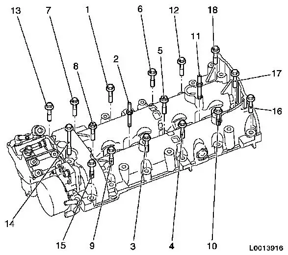
| 47. |
Slacken cylinder head
| • |
Unscrew 10x bolt
Note: Undo bolts in
order shown.
|
|
|
|
| 48. |
Remove cylinder head
Note: Use a second
person
|
| 51. |
Transfer engine short block
|
| 52. |
Clean components and sealing surfaces
|
 Install
| 53. |
Tap guide sleeves into cylinder block
| • |
4x guide sleeve with KM-427
|
|
|
| 54. |
Place rear crankshaft seal ring on EN-46777-10
| • |
Push crankshaft seal ring (3) over EN-46777-10
|
|
|
| 55. |
Install rear crankshaft seal ring (1) with EN-46777-10 (2)
|
|
|
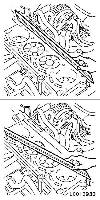
| 57. |
Cylinder Block, Check for Plane Surface
| • |
Check cylinder block with straightedge and feeler gauge on the
sealing surfaces for distortion along their length and
diagonals
|
|
|
|
| 58. |
Adjust TDC combustion stroke - cylinder 1
| • |
Insert MKM-571-B (1) in KM-301 (2)
|
| • |
Place KM-301 with MKM-571-B on cylinder block
|
| • |
Place probe of MKM-571-B on piston
head
|
| • |
Turn engine in direction of rotation
Note: Determine highest
point of cylinder 1 by turning the crankshaft.
|
|
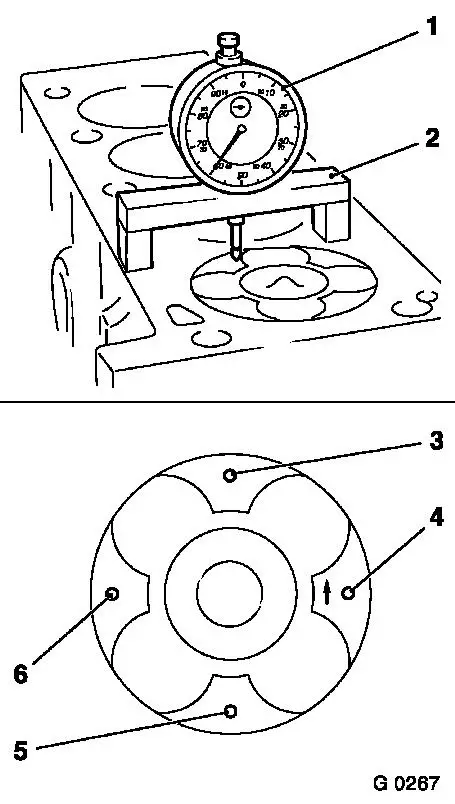
| 59. |
Measure piston projection
| • |
Place probe of MKM-571-B on cylinder
block
|
| • |
Set dial to zero
Note: Note
pre-tension!
| – |
Determine highest point by turning the crankshaft
|
|
| • |
Measure piston projection
| – |
Measure on all 4 pistons
|
| – |
Perform measurements at two different points (3 and 4) or )5
and 6)
|
|
|
|
|
| 60. |
Lock crankshaft
| • |
Insert EN-46778 (1) through flywheel
(2) into cylinder block
|
|
|
|
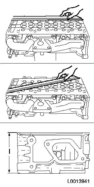
| 61. |
Cylinder Head, Check for Plane Surface
| • |
Check cylinder head with straightedge and feeler gauge on the
sealing surfaces for sag along their length and in the diagonals
for distortion
|
|
| 62. |
Measure height of cylinder head
| • |
Sealing surface to sealing surface
|
| • |
Measurement I: = 105.45 - 105.55
mm
|
|
|
|
Important: The largest piston
projection is decisive for the selection of the cylinder head
gasket with the corresponding marking!
|
| 63. |
Replace cylinder head gasket
| • |
Place cylinder head gasket in position
|
Piston projection
|
Thickness of cylinder head gasket
|
Identification
|
|
0.028 - 0.127 mm
|
0.67 - 0.77 mm
|
without hole
|
|
0.128 - 0.227 mm
|
0.77 - 0.87 mm
|
one hole
|
|
0.228 - 0.327 mm
|
0.87 - 0.97 mm
|
two holes
|
Note: Note guide
sleeves!
|
|
| 64. |
Insert cylinder head
Note: Use a second
person
|
| 65. |
Screw in 10x cylinder head bolt
| • |
Use new bolts
Note: Do not tighten
bolts!
|
|
| 66. |
Align cylinder head
| • |
Align cylinder head (2) with cylinder block (3) using a
straightedge (1)
|
|
|
|
| 67. |
Fasten cylinder head
| • |
Tighten 10x cylinder head bolt 40 Nm +
90° + 90°
Note: Note correct
tightening sequence!
|
|
|
|
| 68. |
Insert 16x roller cam follower
Note: Note removal
sequence!
|
| 69. |
Insert camshaft housing
| • |
Insert new gasket
Note: Note "TOP"
marking
|
| • |
Screw in 2x stud bolt (M8)
|
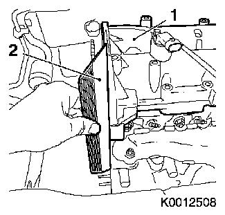
|
| 70. |
Align camshaft housing (1)
| • |
Align with cylinder head using straightedge (2)
|
|
|
|
|
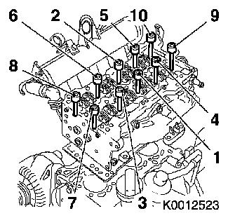
| 71. |
Tighten camshaft housing
| • |
Tighten 2x stud bolt (M8) (2) and (11) 25 Nm
|
| • |
Tighten 16x bolt (M7) 18 Nm
Note: Note longer bolt
lengths (14). Note correct tightening sequence!
|
|
|
| 72. |
Clean 4x injector seat with EN-47632
| • |
Loosen dirt with the brush side (1)
|
| • |
Remove dirt with the sponge side (2)
|
|
|
|
| 73. |
Install 4x injector
| • |
Replace 4x injector shaft seal ring
|
| • |
Replace 4x injector seal ring (1)
|
|
|
|
| 74. |
Attach oil leak line
| • |
Unlock 4x retaining clamp
|
|
| 75. |
Attach timing chain oil spray nozzle
|
| 76. |
Attach timing chain guide rail
|
| 77. |
Insert timing chain with camshaft drive gear and crankshaft
drive gear
|
| 78. |
Fasten camshaft drive gear
| • |
Counterhold with KM-6347 and KM-956-1 on camshaft drive gear
|
|
| 79. |
Attach timing chain tension rail
|
| 80. |
Attach timing chain tensioner
| • |
Tension timing chain tensioner
|
|
|
Important: The timing case must
be fitted within 10 minutes of applying the silicone sealing
compound!
|
| 81. |
Insert timing case gasket
| • |
Apply silicone sealant to the transitions between the cylinder
head and camshaft housing (1) and the cylinder block and cylinder
head (2)
Note: Select a suitable
silicone sealing compound from the spare parts catalogue.
|
|
|
| 82. |
Attach timing case.
| • |
Centre timing case with EN-46775
(1)
|
| • |
Attach engine vent hose to timing case
|
|
|
|
| 83. |
Install front crankshaft seal ring with EN-46776 (1)
|
|
|
| 84. |
Attach torsional vibration damper flange
Note: Left-handed
thread
| • |
Tighten bolt 50 Nm + 90°
| – |
Counterhold with KM-662-C
|
|
|
| 86. |
Check camshaft timing
| • |
Unscrew 2x camshaft reference drift EN-46781
|
| • |
Turn engine 690° in
direction of engine rotation at vibration damper flange bolt
|
| • |
Screw in 2x camshaft reference drift EN-46781
|
| • |
Turn engine in direction of engine rotation by the bolt on the
torsional vibration damper flange until reference drift EN-46781 engages audibly in both camshafts
|
|
| 87. |
Check crankshaft position EN-46778 .
Insert through bore in flywheel.
| • |
Turn crankshaft carefully at bolt for torsional vibration
damper flange until EN-46778 engages in
cylinder block
Note: If EN-46778 cannot be inserted in the cylinder block,
repeat the adjustment procedure.
|
|
| 88. |
Unscrew 2x camshaft reference drift EN-46781
|
| 89. |
Install 2x closure bolt
Note: Complete assembly
within 10 minutes!
| • |
Coat 2 bolts with locking compound
Note: Select a suitable
locking compound from the spare parts catalogue.
|
| • |
Tighten 2x closure bolt 15 Nm
|
|
| 90. |
Fit torsional vibration balancer
|
| 91. |
Attach coolant pump
Note: Use new seal.
Coat seal with silicone grease. Coolant pump journal must point to
oil filler pipe. Select suitable silicone grease from the spare
parts catalogue.
|
| 92. |
Attach ribbed V-belt tensioner
|
| 93. |
Attach right engine damping block adapter
|
| 94. |
Attach crankshaft sensor
|
| 95. |
Attach oil filter housing
| • |
Use new seal
Note: Note different
bolt lengths!
|
|
| 96. |
Attach coolant pipe to cylinder block
Note: Use new seal.
Coat seal with silicone grease. Select suitable silicone grease
from the spare parts catalogue!
|
| 97. |
Attach thermostat housing to cylinder head
| • |
Use new gasket
Note: Coat gasket with
silicone grease. Select suitable silicone grease from spare parts
catalogue.
|
|
| 98. |
Attach thermostat housing coolant pipe to oil filter
housing
Note: Use new
gasket
| • |
Attach coolant hose to thermostat housing.
|
| • |
Attach to oil filter housing
|
| • |
Attach to cylinder block
|
|
| 99. |
Attach exhaust port for cylinder block ventilation
|
| 100. |
Attach oil separator for engine ventilation
| • |
Attach engine vent hose to timing case
|
| • |
Attach engine vent hose to flange
|
|
| 101. |
Attach dipstick guide tube
|
| 102. |
Attach EGR valve with EGR cooler
| • |
Attach exhaust gas recirculation pipe to intake manifold
|
| • |
Attach coolant hose to thermostat housing.
|
|
| 103. |
Install accumulator with bracket
| • |
Tighten 3x bolts 25 Nm
Note: Insert engine
transport shackle.
|
| • |
Attach fuel return line to high-pressure pump
|
| • |
Attach fuel return line
| – |
Connect quick release fitting
|
|
| • |
Connect 2x wiring harness plugs
|
|
| 104. |
Install high pressure lines
| • |
Use new high pressure lines
|
| • |
Install 4x accumulator high-pressure lines to injector
| – |
Tighten 4x union nut M12 24 Nm
|
| – |
Tighten 4x union nut M14 28 Nm
|
|
| • |
Install high pressure line - high pressure pump to
accumulator
| – |
Tighten union nut M12 24 Nm
|
| – |
Tighten union nut M14 28 Nm
|
|
|
| 105. |
Install fuel supply line
| • |
Attach fuel line to high-pressure pump
|
| • |
Tighten 3x bolts
Note: Note 2x ground
cable!
|
| • |
Clip vacuum line into bracket
|
|
| 106. |
Attach wiring harness for motor
|
| 107. |
Connect engine wiring harness on exhaust side
| • |
Connect wiring harness plug of rail pressure sensor
|
| • |
Connect charge pressure sensor wiring harness plug
|
| • |
Connect wiring harness plug of rail pressure regulator
|
| • |
Connect EGR valve wiring harness plug
|
|
| 108. |
Attach engine wiring harness on intake side
| • |
Connect 4x injector wiring harness plug
|
| • |
Connect 4x wiring harness plug, sheathed glow plug
|
| • |
Connect wiring harness plug, camshaft sensor
|
| • |
Connect wiring harness plug of crankshaft sensor
|
| • |
Connect coolant temperature sensor wiring harness plug
|
|
| 110. |
Apply sealing compound
Note: Apply a bead of
silicone sealant on the sealing surface of the oil pan.
Note: Select a suitable
silicone sealing compound from the spare parts catalogue.
|
|
|
Important: The oil pan must be
fitted within 10 minutes of applying the silicone sealing
compound
|
| 111. |
Install oil pan
| • |
To cylinder block base plate
|
| • |
Connect engine oil level wiring harness plug
|
|
| 112. |
Install transmission bracket
| • |
To cylinder block base plate
|
| • |
To transmission
Note: Note different
bolt lengths!
|
|
| 114. |
Fill and correct engine oil level
| • |
Observe specified oil quantity
|
|
| 115. |
Install thrust plate with clutch disc
|
| 116. |
Fit starter
| • |
Attach 2x wiring harness
|
|
| 117. |
Attach transmission to engine
- For transmission F17-5 and M20-6
- For manual transmission M20-6 MTA
|
1 ) ; protective caps are available in the parts
catalogue
|
