|
Cylinder Head, Remove and Install
Note: Only remove
cylinder head with the engine cold.
 Remove Remove
| 2. |
Disconnect ground cable from battery
|
| 3. |
Remove air cleaner housing 
|
| 5. |
Detach camshaft sensors from timing case
| • |
Exhaust camshaft sensor
|
|
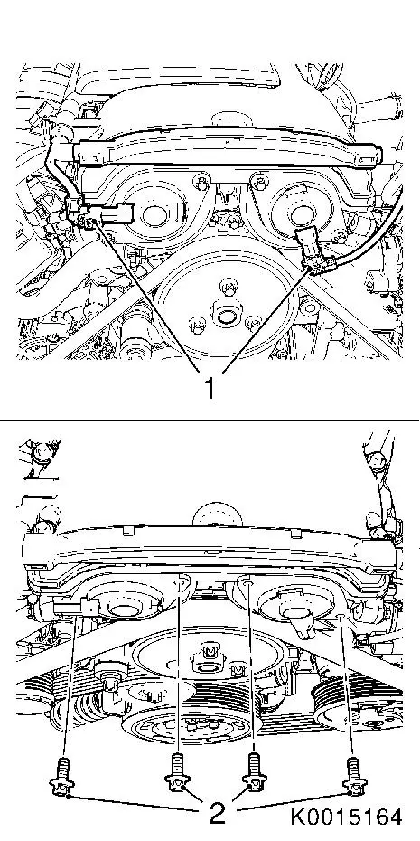
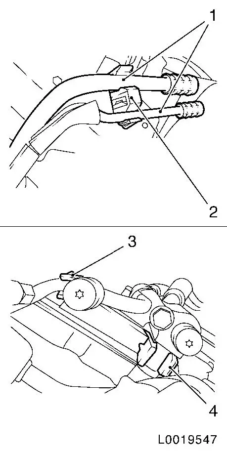
| 6. |
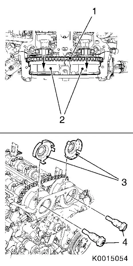
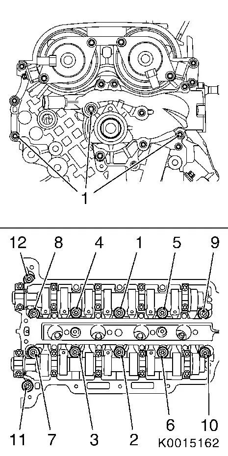
Release camshaft adjuster Hall-effect sensors
| • |
Disconnect 2 wiring harness plugs (1)
|
|
|
|
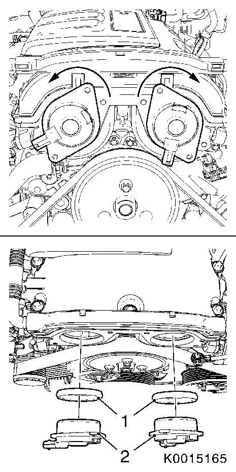
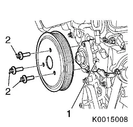
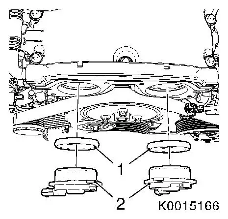
| 7. |
Remove camshaft adjuster Hall-effect sensors (2)
| • |
Rotate camshaft adjuster Hall-effect sensors as shown in the
graphic
| – |
Rotate intake side to the left
|
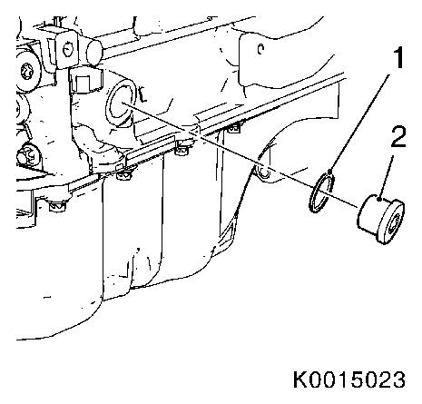
| – |
Rotate exhaust side to the right
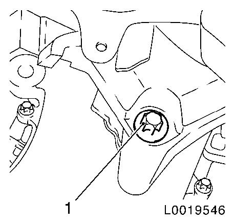
|
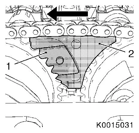
|
| • |
Remove camshaft adjuster Hall-effect sensors
|
| • |
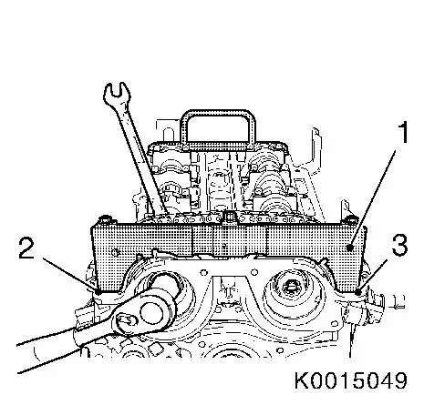
Remove camshaft adjuster Hall-effect sensor seal ring (1)
|
|
|
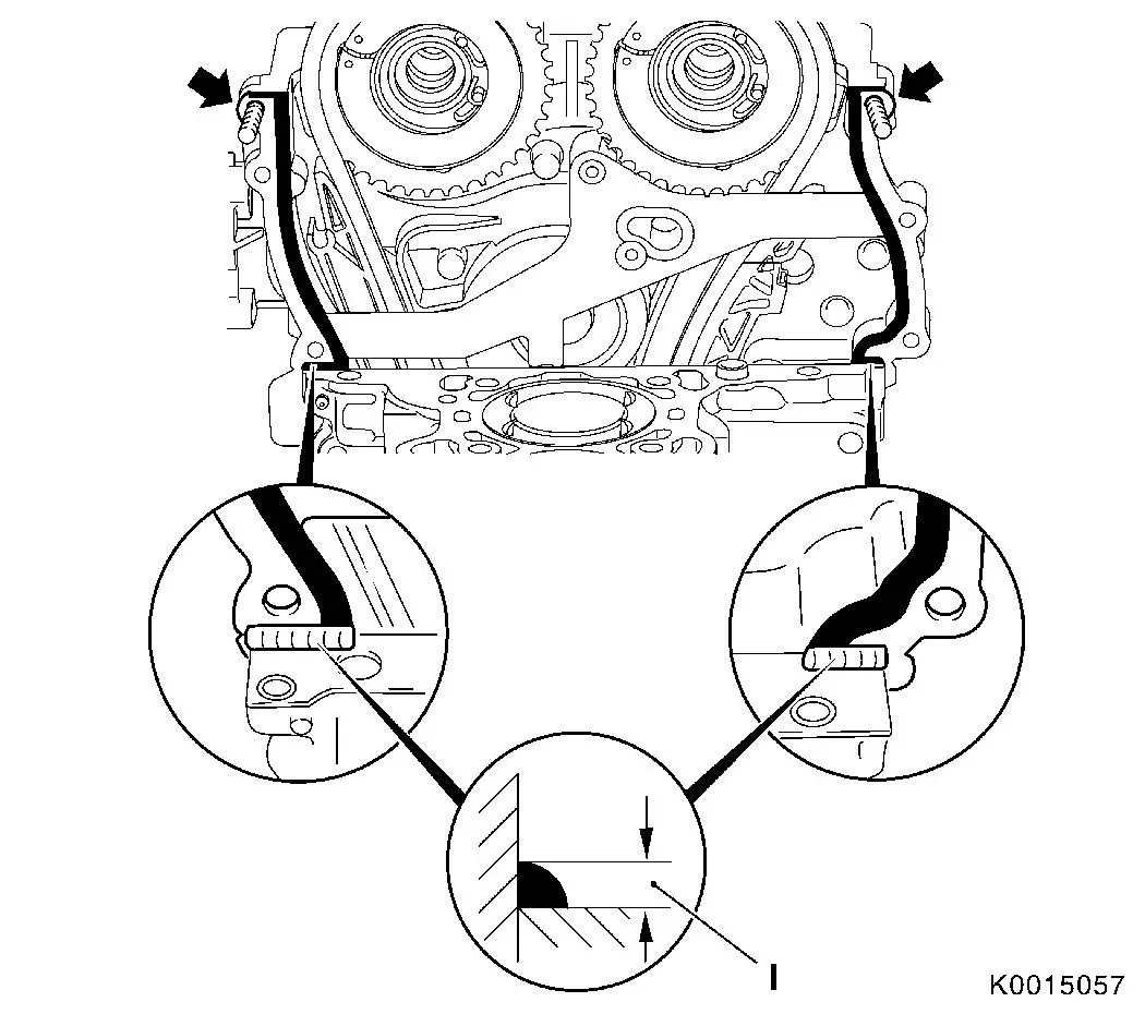
|
| 8. |
Remove exhaust manifold
|
| 9. |
Remove intake manifold
|
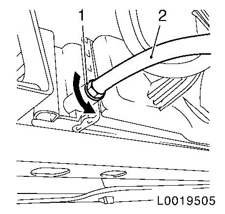
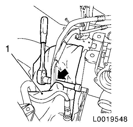
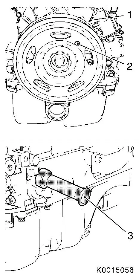
| 10. |
Drain coolant
| • |
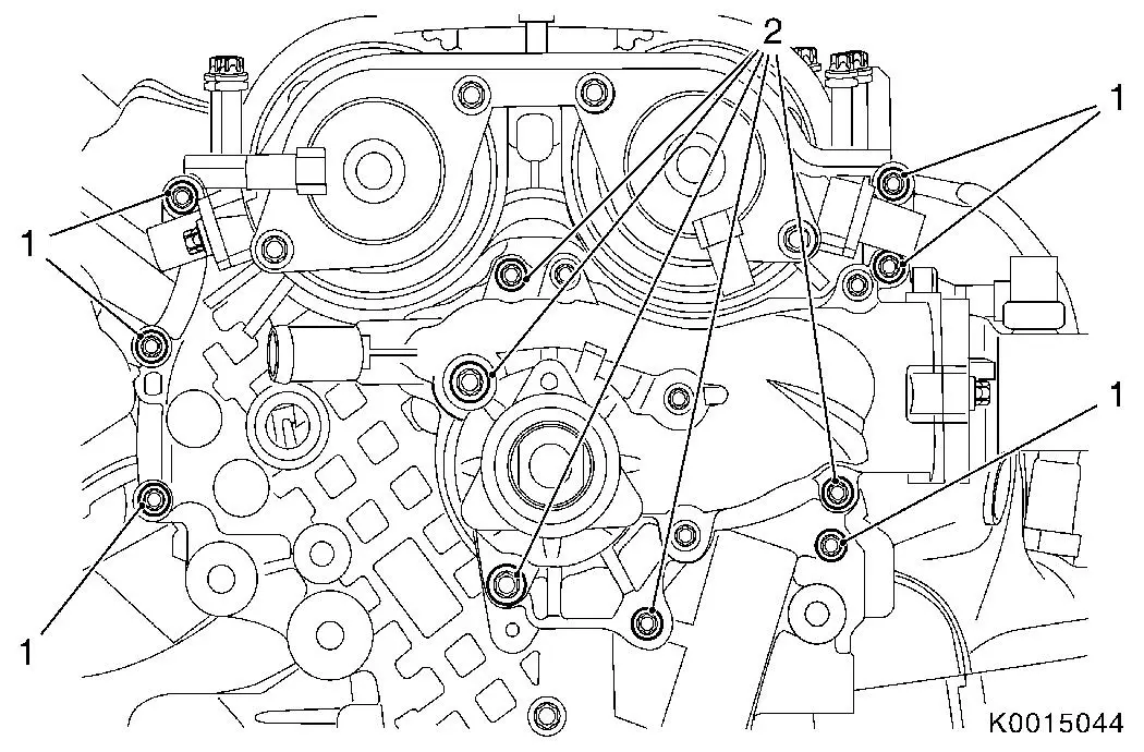
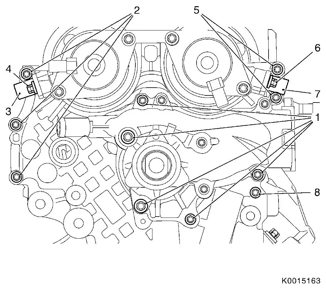
Place collecting basin underneath.
|
| • |
Push on suitable hose (2)
|
| • |
Open drain cock (1) in the direction of the arrow
|
|
|
|
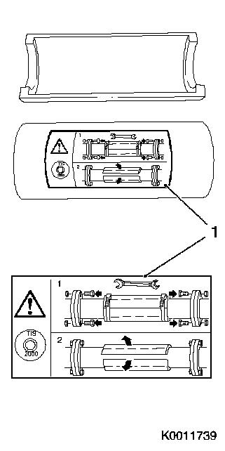
Important: When removing the
centre silencer, a catalytic converter, an exhaust manifold or an
exhaust manifold with catalytic converter, the exhaust system piece
remaining in the vehicle must be secured against uncontrolled
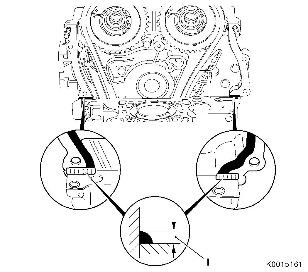
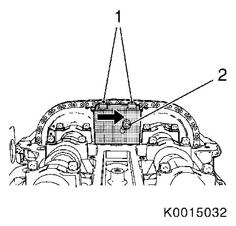
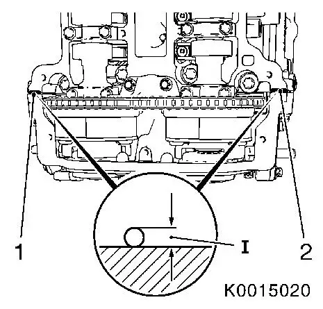
sagging. Bends in the flex pipe by as little as 5 - 10 angle
degrees or a twist through ± 0.5 ° from the specified
installation position can lead to damage with subsequent complete
failure of the flex pipe. The exhaust system fastening clamps must
be replaced every time they are removed. When replacing the exhaust
system, the transport fixing must first be removed after
installation and before commissioning. This should be stored for
other work in which the exhaust system must be removed and used to
secure the flex pipe.
|
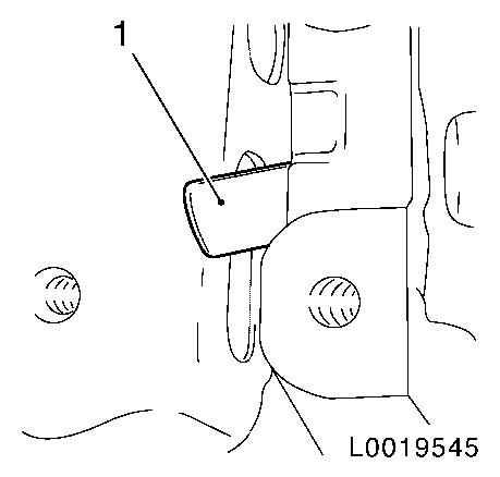
| 11. |
Attach transport fixing to flex pipe.
Note: The installation
instruction (1) on the transport fixing must be observed.
|
|
|
| 12. |
Separate wiring harness catalytic converter control
|
| 13. |
Detach front exhaust pipe (2) from catalytic converter
|
|
|
| 14. |
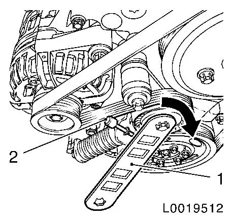
Remove ribbed V-belts from alternator and compressor
Note: For vehicles with
climate control system.
| • |
Mark direction of rotation
|
| • |
Tension the ribbed V-belt tensioner using EN-48488 (1) in the direction of the arrow
|
| • |
Relieve tension on ribbed V-belt tensioner
|
|
|
|
| 15. |
Disconnect compressor wiring harness plug
Note: For vehicles with
climate control system.
|
| 16. |
Detach compressor from engine block and timing case
Note: For vehicles with
climate control system.
| • |
Fasten the compressor to the chassis using securing wire
|
|
| 17. |
Detach coolant connection from cylinder head
| • |
Disconnect wiring harness plug for coolant temperature
sensor
|
| • |
Secure coolant connection on battery support by suitable
means
|
|
| 18. |
Remove ribbed V-belt
| • |
without air conditioning
Note: An appropriate
engine crane is used to remove the right engine damping block and
the engine damping block support.
|
|
| 19. |
Remove cylinder head cover
|
| 20. |
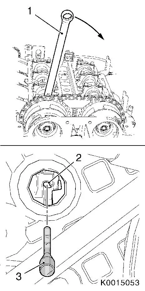
Lower engine
Important: Ensure that the
chassis paint is not damaged.
|
| • |
Insert a plastic or wood wedge (1) between the chassis and the
engine damping block support
|
|
| 21. |
Loosen coolant lines (1)
| • |
Unclip from 3 brackets (2), (3) and (4)
|
| • |
Rotate bracket (2) by 90°
|
|
|
|
| 22. |
Detach engine damping block support from timing case
Important: Ensure that the
chassis paint is not damaged.
|
| • |
Insert rags (1)
|
| • |
Route the extension through the coolant lines (arrow)
|
|
|
|
| 23. |
Loosen lower engine damping block support
| • |
Take out support upwards
|
|
|
|
| 24. |
Raise engine
| • |
Remove plastic or wood part
|
|
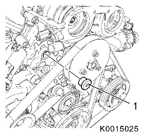
| 25. |
Detach coolant pump belt pulley (1) from coolant pump
|
|
|
|
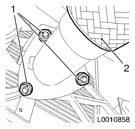
| 26. |
Slacken timing case
| • |
Unscrew 5x bolts, coolant pump (1)
|
| • |
Unscrew 6x timing case bolt (2)
|
|
|
| 27. |
Attach top support for engine damping block
Important: Ensure that the
chassis paint is not damaged.
|
| • |
Insert cloths between body and ratchet or torque wrench
|
|
| 28. |
Lower engine
Important: Ensure that the
chassis paint is not damaged.
|
| • |
Insert a plastic or wood wedge between the chassis and the
engine damping block support
|
|
| 29. |
Fasten lower engine damping block support
|
| 30. |
Raise engine to normal height
| • |
Remove plastic or wood part
|
|
| 31. |
Fit engine damping block to body
|
| 32. |
Attach engine damping block to engine damping block support
|
| 33. |
Remove cylinder block base plate locking screw (2) with seal
ring (1)
|
|
|
| 34. |
Adjust TDC of combustion stroke of cylinder 1
| • |
Marking on the crankshaft belt pulley marker bore (2) must
align with the cast projection (1) on the timing case
|
| • |
Turn crankshaft evenly until KM-952
engages
|
| • |
Insert KM-952 (3) to the stop.
|
|
|
|
| 35. |
Remove closure bolt of chain tensioner (1) from timing case
|
|
|
| 36. |
Lock chain tensioner (2) using KM-955-1 (3) -- to do this, tension the intake
camshaft via the hexagon and using the open-end spanner (1) in the
direction of engine rotation (direction of arrow)
|
|
|
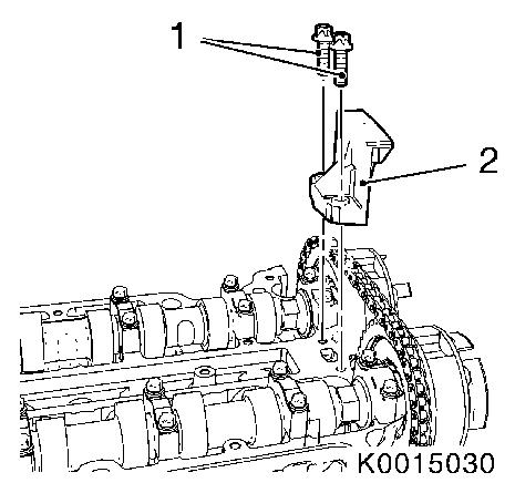
| 37. |
Detach upper sliding rail (2) from cylinder head
|
|
|
| 38. |
Detach camshaft sprockets
| • |
Counterhold with open-ended wrench against the hexagon of the
camshafts
|
| • |
Remove phase sensor discs (3)
|
| • |
Pull camshaft sprockets (2) from camshafts
|
| • |
Set aside camshaft sprockets (2) with timing chain (1) in
timing case and secure with cable tie
|
|
|
|
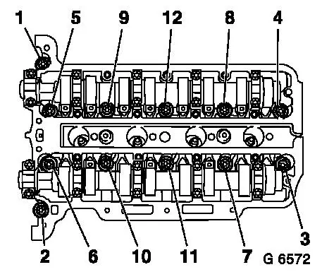
| 39. |
Remove cylinder head bolts
Note: Undo cylinder
head bolts in the order shown.
|
| 40. |
Remove cylinder head
Note: Use a second
person.
| • |
Draw chain tensioner past the tension rail
|
| • |
Place cylinder head on wooden blocks
|
| • |
Remove cylinder head gasket
|
|
|
|
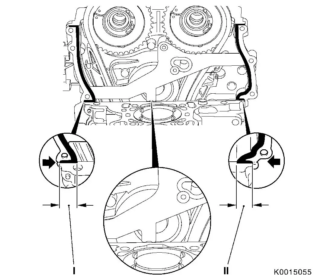
| 41. |
Cut away timing case gasket
| • |
Cut through elastomer sealing lips (dimension I and II) of the
timing case gasket with a sharp knife from inside to outside so
that they are flush on the cylinder block
|
| • |
Bend and snap gasket carefully at the fracturing points
provided (arrows)
|
|
|
|
| 42. |
Remove gasket remnants and clean sealing surfaces
Note: Ensure that no
residues of the elastomer sealing lips remain at the connection
points between the timing case and cylinder block and no residues
from the gasket drop into the timing case.
|
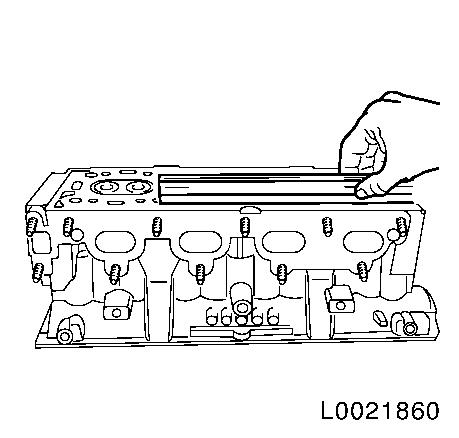
| 43. |
Check cylinder head and cylinder block with a straightedge
Note: Before carrying
out the check, carefully remove any old gasket residues from the
cylinder head sealing surface and the cylinder block surface. Do
not use any metal, sharp-edged tools when cleaning. Ensure that the
cylinder head sealing surface and the cylinder block surface are
not damaged.
| • |
Sealing surface for bend, lengthways and widthways
|
| • |
Check sealing surface for distortion in the diagonal
|
|
|
|
| 44. |
If the cylinder head is to be checked or overhauled:
| • |
Detach all remaining external attaching parts from the cylinder
head
|
|
 Install
|
| 45. |
Cylinder Head Gasket, Replace
Note: After applying
the silicone sealing compound, the cylinder head must be brought
into position within 10 minutes and the cylinder head bolts and the
timing case bolt must be screwed in loosely.
| • |
Place new cylinder head gasket on cylinder block
| – |
With TOP/OBEN marking at the top
|
|
| • |
Apply a bead of silicone sealing compound approx. 2 mm thick in
the corner between the timing case/cylinder block
|
| • |
Press on in the area of the silicone sealing compound
|
|
|
| 46. |
Adjust timing case gasket to fit at the top (1)
| • |
Insert 2x bolt, timing case (arrows)
|
| • |
Position new part gasket on timing case
|
| • |
Press on in the area of the silicone sealing compound
|
| • |
Apply a bead of silicone sealing compound in the corner between
the timing case/cylinder head gasket
| – |
Approx. 2 mm thick (dimension I)
|
|
|
|
|
| 47. |
Position cylinder head
Note: Use a second
person.
| • |
Guide KM-955-1 through opening in
timing case
|
| • |
Draw chain tensioner past the tension rail
|
| • |
Insert pin in guide rail
|
|
| 48. |
Fasten cylinder head
Important: Use new bolts.
|
| • |
Screw in cylinder head bolts a few thread turns
|
| • |
Attach timing case.
Note: Position cylinder
head in the direction of the timing case by striking it gently with
a rubber mallet.
|
| • |
Tighten 3x bolt (1) 8 Nm
|
Important: Note correct
tightening sequence.
|
| • |
Tighten 12 cylinder head bolts 35 Nm +
180°
|
|
|
|
| 50. |
Remove engine damping block, right hand side
| • |
Unscrew 6x bolts
Note: An appropriate
engine crane is used to remove the right engine damping block and
the engine damping block support.
|
|
| 51. |
Lower engine
Important: Ensure that the
chassis paint is not damaged.
|
| • |
Insert a plastic or wood wedge (1) between the chassis and the
engine damping block support
|
|
|
|
| 52. |
Loosen lower engine damping block support
|
|
|
| 53. |
Raise engine
| • |
Rotate the hexagon of the chain case until the upper bolts of
the engine damping block support are accessible
|
| • |
Remove plastic or wood part
|
|
| 54. |
Detach engine damping block support from timing case
Important: Ensure that the
chassis paint is not damaged.
|
| • |
Insert rags (1)
|
| • |
Route the extension through the coolant lines (arrow)
|
| • |
Take out support upwards
|
|
|
|
| 55. |
Fasten timing case
| • |
Release lower 3 bolts (screws fitted beforehand) from cylinder
head again
|
| • |
Install coolant pump bolts
| – |
Tighten 5x bolt (1) 8 Nm
|
|
| • |
Install timing case bolts
| – |
Tighten 6x bolt (2), (5) and (8) 8
Nm
|
|
| • |
Attach camshaft sensor (3) and (7) with new seal ring
| – |
Tighten bolt (4) and (6) 8 Nm
|
|
|
|
|
| 56. |
Turn camshafts by the hexagon (short distance) until KM-953-A can be inserted in the grooves of the
camshafts
Note: Rotate camshafts
carefully and smoothly. KM-953-A must
engage as far as the stop in the grooves of the camshafts
|
| 57. |
Clean phase sensor discs and camshaft sprockets
Note: The following
steps are to be performed to avoid rotating the phase sensor disc
when tightening the camshaft sprocket.
| • |
Clean the contact surface of the phase sensor disk to the
camshaft sprocket
|
| • |
Clean the contact surface of the camshaft sprocket to the phase
sensor disk
|
| • |
Lightly coat the bolt collar of the bolt with engine oil
|
|
| 58. |
Attach camshaft sprockets
| • |
Position camshaft sprockets on camshafts with timing chain
|
| • |
Hold phase sensor disc on camshaft
|
| • |
Tighten 2x bolt, camshaft sprockets, hand-tight
Note: It must still be
possible to turn the phase sensor discs by hand.
|
|
| 59. |
Apply / attach locating tool EN-49977-200 (2)
| • |
The teeth of the locating tool (1) must engage in the teeth of
the intake camshaft sprocket
Note: Press locating
tool in direction of arrow to ensure that it engages without
play.
|
|
|
|
| 60. |
Tighten locating tool EN-49977-200
| • |
Press locating tool in direction of arrow
|
| • |
Tighten 2x fastening bolt (1)
|
| • |
Tighten adjusting bolt (2)
|
|
|
|
| 61. |
Attach locating tool EN-49977-100 (1)
| • |
Turn phase sensor discs in such a way that EN-49977-100 (1) can be inserted on the timing
case
|
| • |
Tighten 3x fastening bolt
Note: It is possible
that the tool has been applied in the wrong position. Ensure that
there is no play between the fixing tool and the cylinder head at
points (2) and (3).
|
|
|
|
| 63. |
Fasten camshaft sprockets
Note: Tightening torque
10 Nm serves to fix the camshaft
sprockets and the phase sensor disc temporarily.
| • |
Tighten 2x bolt 10 Nm
Note: First of all
tighten bolt of intake camshaft sprocket.
|
| • |
Counterhold the camshafts on the hexagon
|
|
| 64. |
Remove locating tools EN-49977-100 ,
KM-953-A and KM-952
Note: Locating tools
may not be used for counterholding.
|
| 65. |
Tighten camshaft sprockets
Note: Use a second
person.
| • |
Tighten 2x bolt 50 Nm + 60°
|
|
| 66. |
Timing, Check
| • |
Turn crankshaft through 720°
|
| • |
Insert KM-953-A into camshafts
|
| • |
Attach EN-49977-100 on phase sensor
disc
Note: If EN-49977-100 cannot be inserted, the operation
"timing, adjust" must be repeated.
|
|
| 67. |
Remove EN-49977-100 , KM-953-A and KM-952
|
| 68. |
Attach chain tensioner closure bolt to timing case 50 Nm
|
| 69. |
Attach closure bolt with new seal ring to cylinder block base
plate 40 Nm
|
| 70. |
Apply sealing compound
| • |
Disconnect projecting part of timing case gasket (1) flush with
cylinder head/timing case
|
| • |
Apply a bead of silicone sealing compound approx. 2 mm thick
(dimension I)
Note: The cylinder head
cover must be fitted within 10 minutes of applying the silicone
sealing compound.
|
|
|
|
| 71. |
Attach cylinder head cover
|
| 72. |
Attach coolant hose to coolant pump
|
| 74. |
Connect compressor wiring harness plug
|
| 75. |
Insert ribbed V-belt
| • |
without air conditioning
|
|
| 76. |
Attach top support for engine damping block
| • |
Apply the ribbed V-belt on the coolant pump belt pulley
|
Important: Ensure that the
chassis paint is not damaged.
|
| • |
Insert cloths between body and ratchet or torque wrench
|
|
| 77. |
Clip in 4 coolant lines
|
| 78. |
Lower engine
Important: Ensure that the
chassis paint is not damaged.
|
| • |
Insert a plastic or wood wedge between the chassis and the
engine damping block support
|
|
| 79. |
Fasten lower engine damping block support
|
| 80. |
Raise engine to normal height
| • |
Remove plastic or wood part
|
|
| 81. |
Fit engine damping block to body
|
| 82. |
Attach engine damping block to engine damping block support
|
| 83. |
Install intake manifold
|
| 84. |
Install exhaust manifold
|
| 85. |
Attach engine management wiring harness
| • |
Connect engine management wiring harness
|
| • |
Connect 14x wiring harness plugs
|
| • |
Screw in 3x earth cable
|
|
| 86. |
Attach front exhaust pipe to exhaust manifold with new gasket
and new nuts
|
| 87. |
Connect wiring harness plug for throttle valve module
|
| 88. |
Insert camshaft adjuster Hall-effect sensors (2)
| • |
Insert camshaft adjuster Hall-effect sensor seal ring (1)
|
| • |
Screw in camshaft adjuster Hall-effect sensors
|
|
|
|
| 89. |
Tighten camshaft adjuster Hall-effect sensors
| • |
Screw in 4x bolt (2)
| – |
Tightening torque 8 Nm .
|
|
| • |
Connect 2x wiring harness plug (1)
|
|
|
|
| 91. |
Install air cleaner housing
|
| 92. |
Connect wiring harness plug, tank vent valve
|
| 93. |
Check engine oil level, correct if necessary
|
| 94. |
Connect ground cable to battery
|
| 95. |
Fill and bleed cooling system
|
| 96. |
Program volatile memories
|
|
