|
Repair engine using a short block engine
 Remove Remove
| 2. |
Remove manual transmission from engine 
|
| 3. |
Detach thrust plate and clutch disk
|
|
|
| 5. |
Attach engine to suitable engine overhaul stand
| • |
Attach KM-2358 to 3x engine transport
shackle
|
| • |
Raise using engine crane
|
| • |
Attach engine to engine overhaul stand
|
| • |
Detach KM-2358 from 3x engine
transport shackle
|
|
| 6. |
Drain engine oil
| • |
Place collecting basin underneath.
|
| • |
Remove oil filter housing cover
|
| • |
Remove oil filter element
|
|
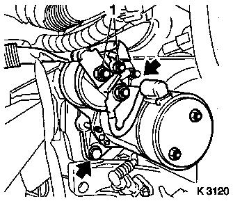
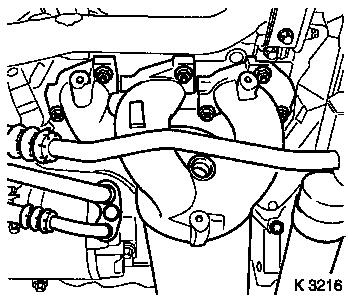
| 7. |
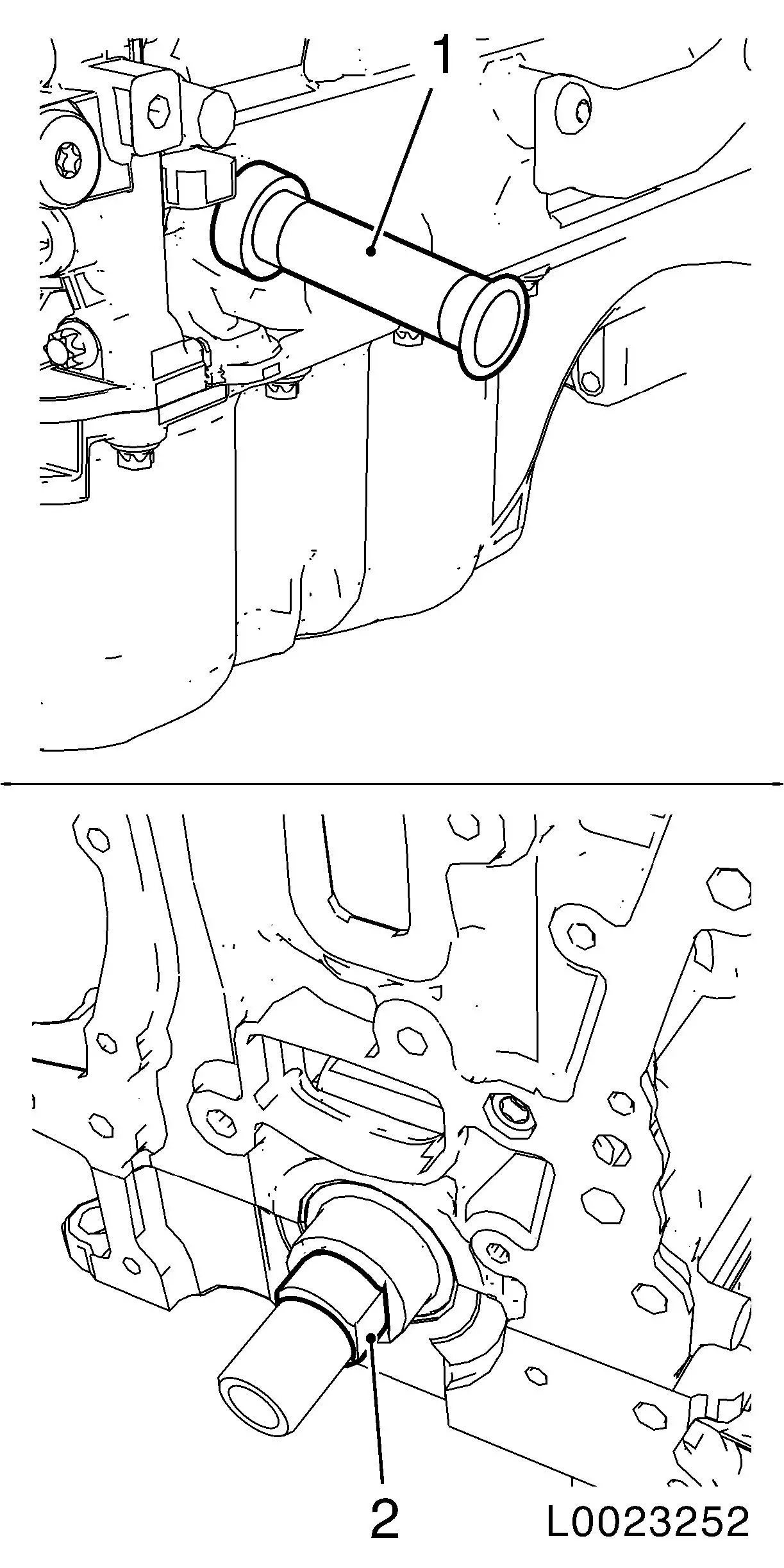
Detach right engine damping block bracket (1)
|
| 8. |
Screw in oil drain bolt
|
|

|
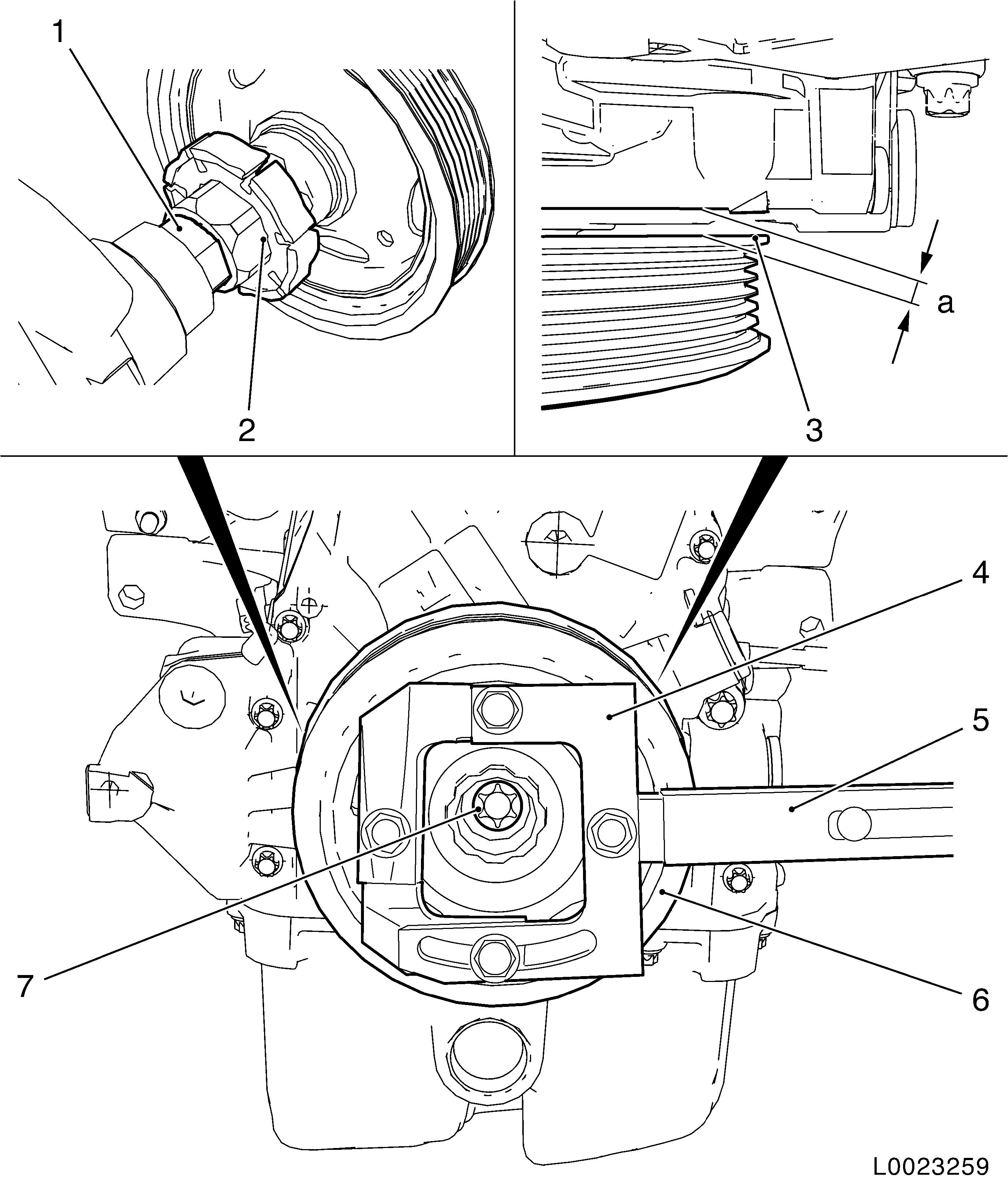
| 9. |
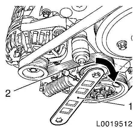
Detach ribbed V-belt
| • |
Mark direction of rotation
|
| • |
Tension the ribbed V-belt tensioner using KM-6131 (1) in the direction of the arrow
|
| • |
Release ribbed V-belt tensioner
|
|
|
|
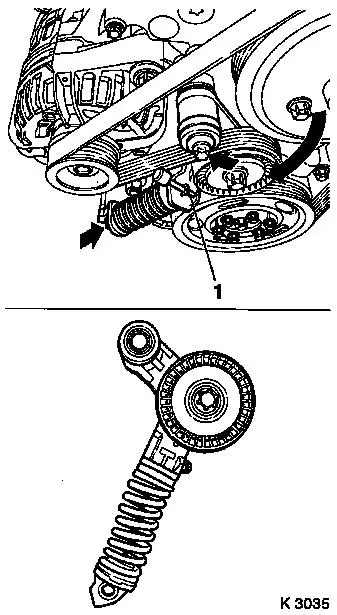
| 10. |
Remove ribbed V-belt tensioner
| • |
Tension the ribbed V-belt tensioner using KM-6131 in the direction of the arrow
|
| • |
Release ribbed V-belt tensioner
|
| • |
Unscrew 2 bolts (arrows)
|
| • |
Remove ribbed V-belt tensioner
|
|
|
|
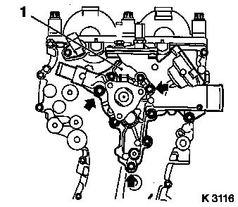
| 11. |
Detach coolant pump ribbed V-belt pulley
| • |
Unscrew 3x bolts
Note: Counterhold with
open-end wrench
|
|
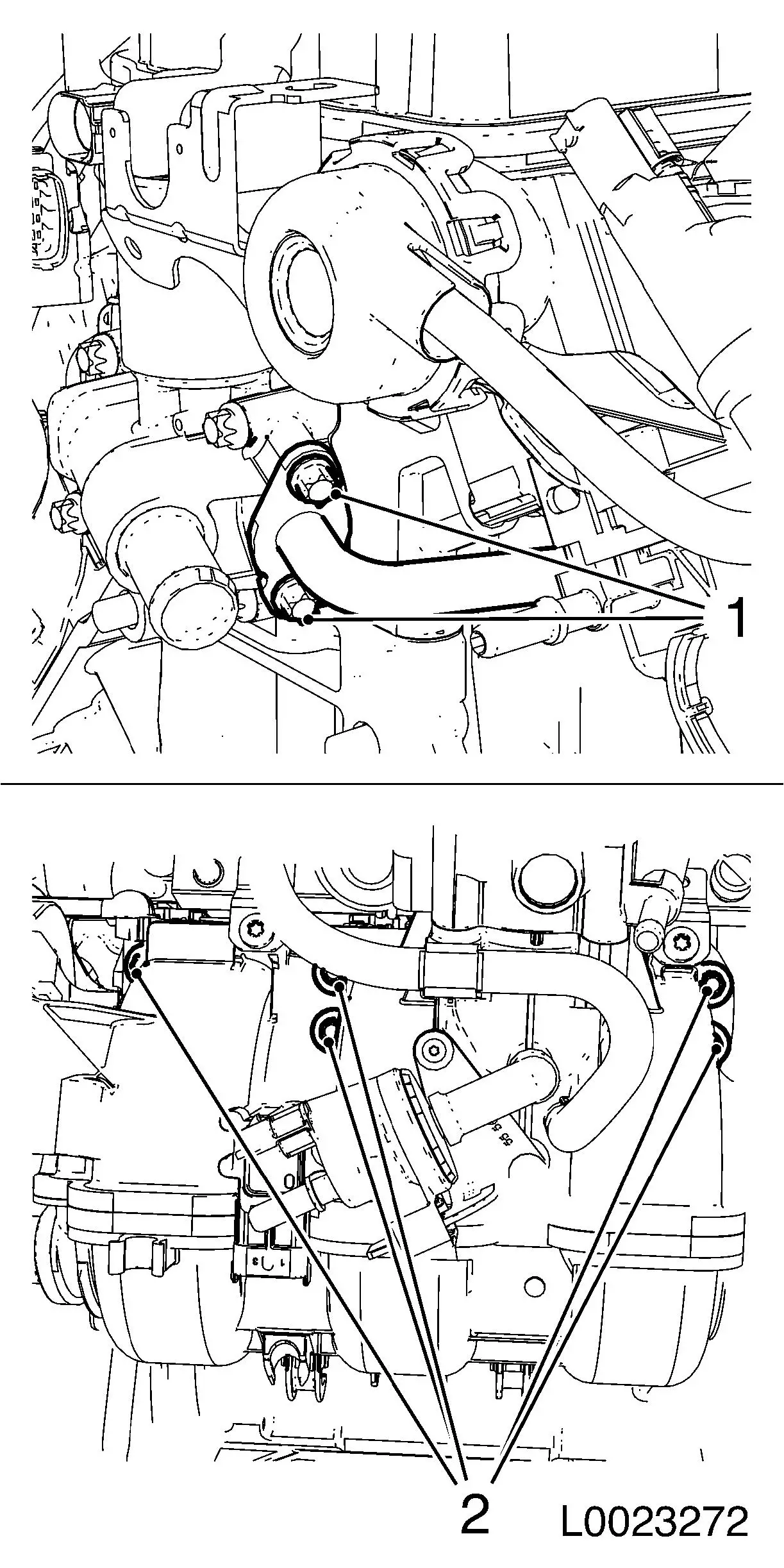
| 12. |
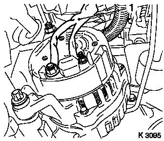
Detach alternator
| • |
Release alternator wiring harness (1)
|
| • |
Detach 2x bolted connections
|
|
|
|
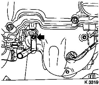
| 13. |
Detach starter
| • |
Detach starter wiring harness
|
| • |
Unscrew 2 bolts (arrows)
|
|
|
|
|
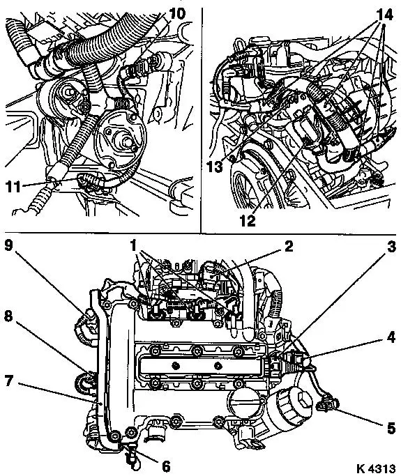
| 14. |
Detach engine management wiring harness
| • |
Separate 11x wiring harness for engine management
| – |
Oil pressure switch (6), coolant temperature sensor (8),
camshaft sensor (9), throttle valve module (2). engine control unit
(12), exhaust gas recirculation valve (4), ignition module (3),
knock sensor (10), crankshaft sensor (11), injectors (1)
|
|
| • |
Detach engine control unit earth cable (13)
|
| • |
Unclip wiring trough (7)
|
|
|
| 15. |
Detach 3x coolant hoses from coolant pump
|
| 16. |
Detach coolant hose from coolant flange exhaust gas
recirculation valve
|
| 17. |
Detach coolant pump (1) together with thermostat housing
Note: When removing
guide sleeves, please note
| • |
Place collecting basin underneath.
|
| • |
Unscrew 9x bolts
Note: Note differing
bolt lengths (arrows = short bolts)
|
|
|
|
| 18. |
Loosen oil dipstick guide tube
|
| 19. |
Remove oil dipstick guide tube
| • |
Rotate oil dipstick guide tube forward
|
|
|
|
| 20. |
Remove exhaust manifold heat shield
| • |
Unclip oxygen sensor mixture regulator wiring harness plug
|
|
| 21. |
Remove exhaust manifold
| • |
Undo 2x bolt from catalytic converter bracket
|
|
|
|
| 22. |
Remove intake manifold
| • |
Detach vent hose from cylinder head cover
|
| • |
Detach EGR pipe from exhaust gas recirculation valve
|
| • |
Remove 3x intake manifold seal
|
|
|
|
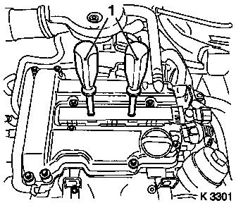
| 24. |
Detach ignition module
| • |
Detach ignition module cover
|
| • |
Pull out using KM-6009 (1)
Note: Do not tilt
|
|
| 25. |
Remove cylinder head cover
|
|
|
|
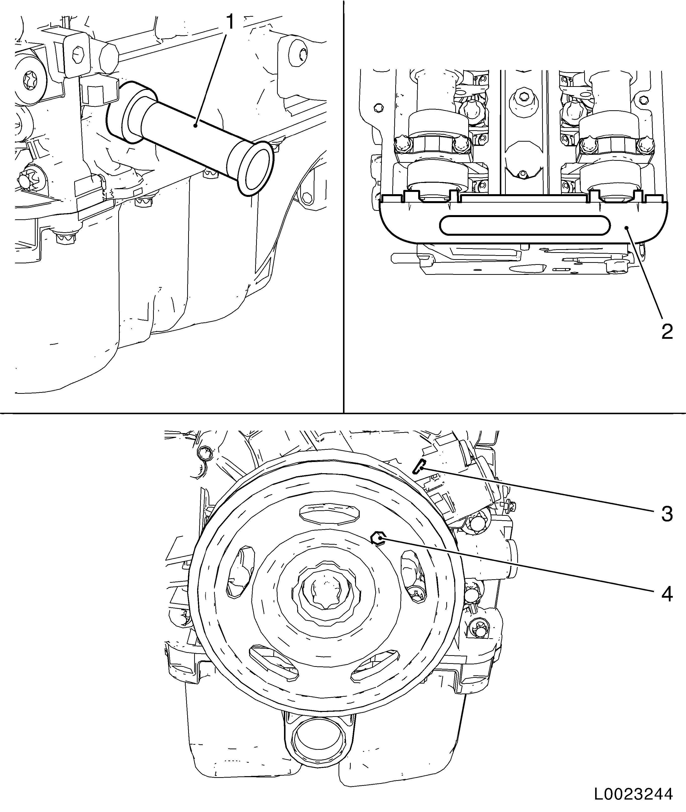
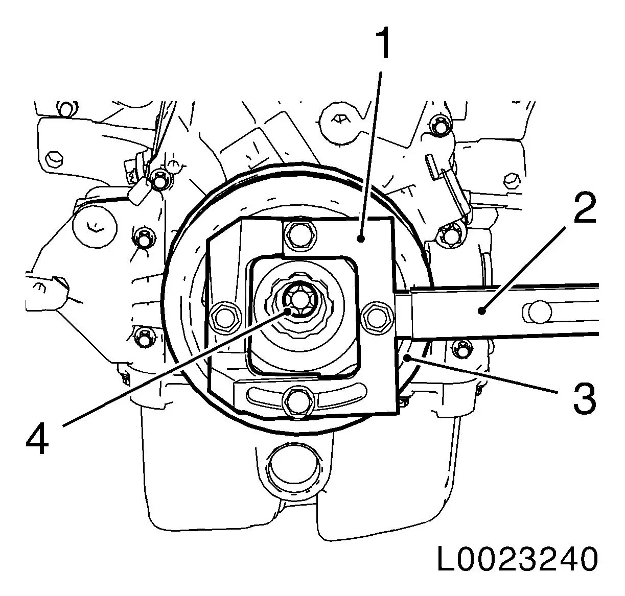
| 26. |
Set engine to TDC of combustion stroke of cylinder 1
| • |
Unscrew crankshaft closure bolt
|
| • |
Rotate crankshaft in direction of engine rotation to the
marking (4) on the torsional vibration damper and align with
marking (3) on timing case
|
Important: It must be possible to
insert EN-953 smoothly and without major
effort into the camshaft grooves.
|
| • |
Lock camshafts with EN-953 (2)
|
Important: It must be possible to
insert KM-952 smoothly and without major
effort into the crankshaft recess.
|
| • |
Fix crankshaft with KM-952 (1)
|
|
|
| 27. |
Detach torsional vibration damper (3)
| • |
Counterhold it with EN-49979 (1)
together with KM-956-1 (2)
|
|
|
|
| 28. |
Rotate engine on engine overhaul stand through 180°
|
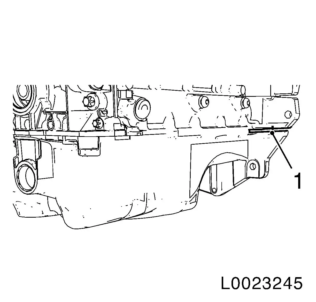
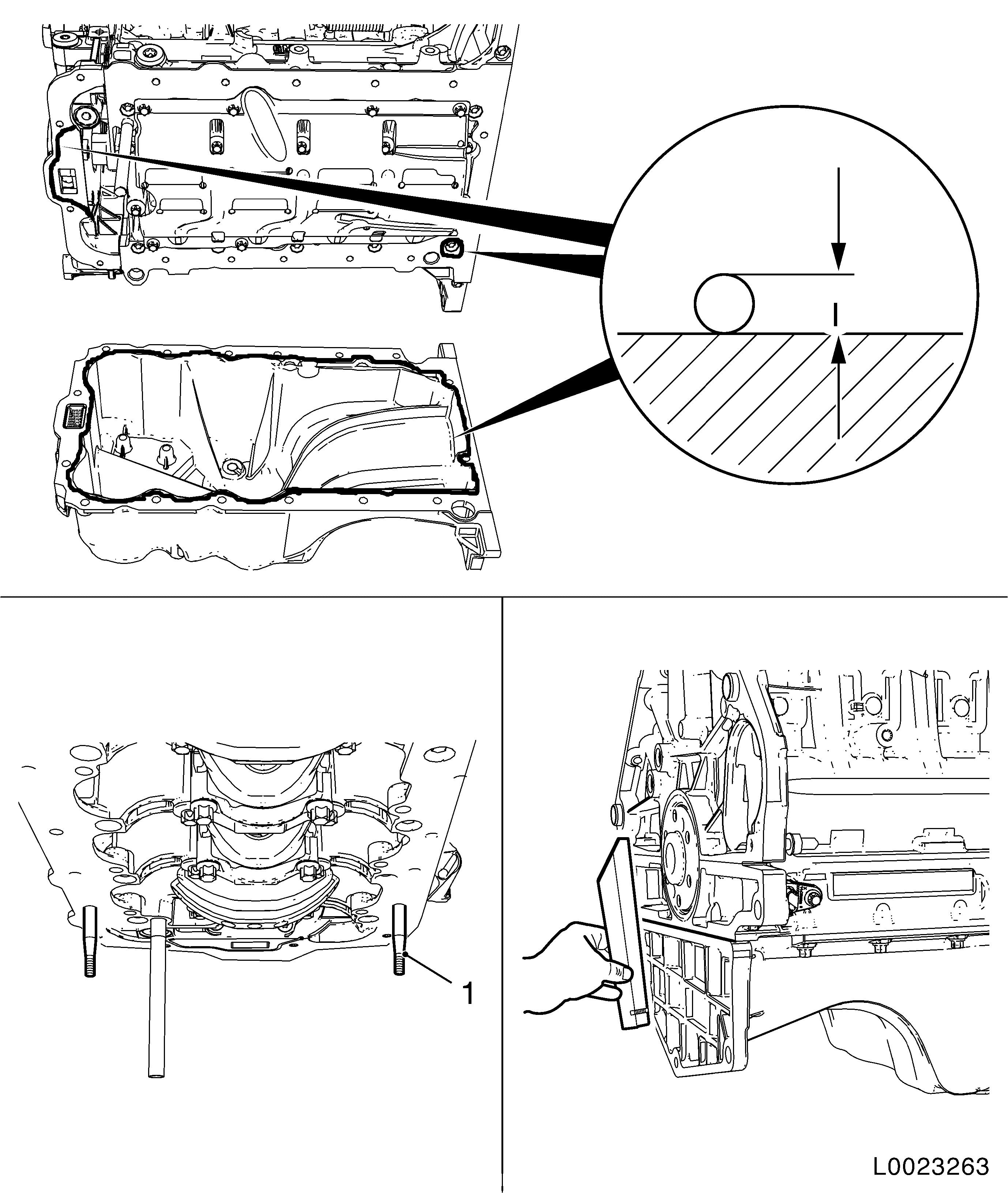
| 29. |
Remove oil pan
Important: Do not damage oil pan
and base place seal surfaces when prising off
|
| • |
Detach oil pan by carefully prising out to position (1)
|
|
|
|
| 30. |
Detach oil baffle plate
|
| 31. |
Rotate engine on engine overhaul stand through 180°
|
|
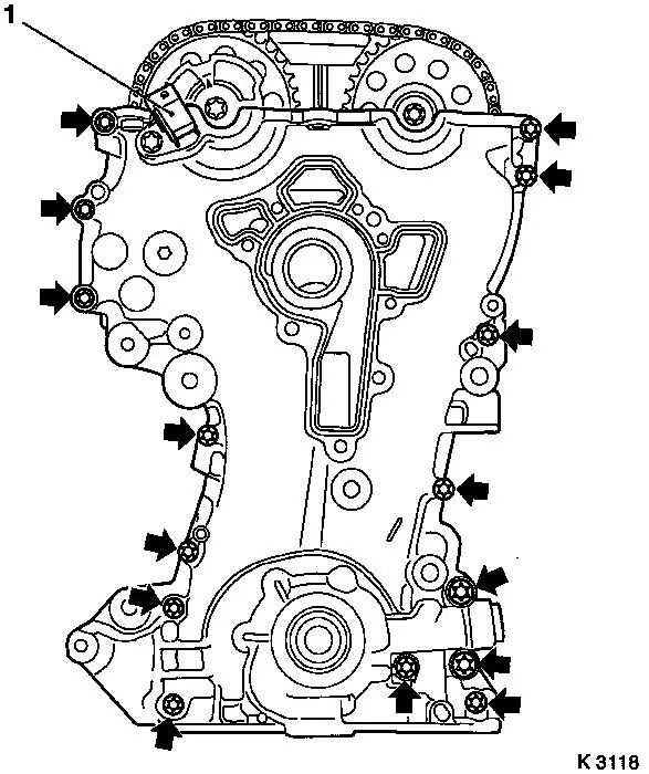
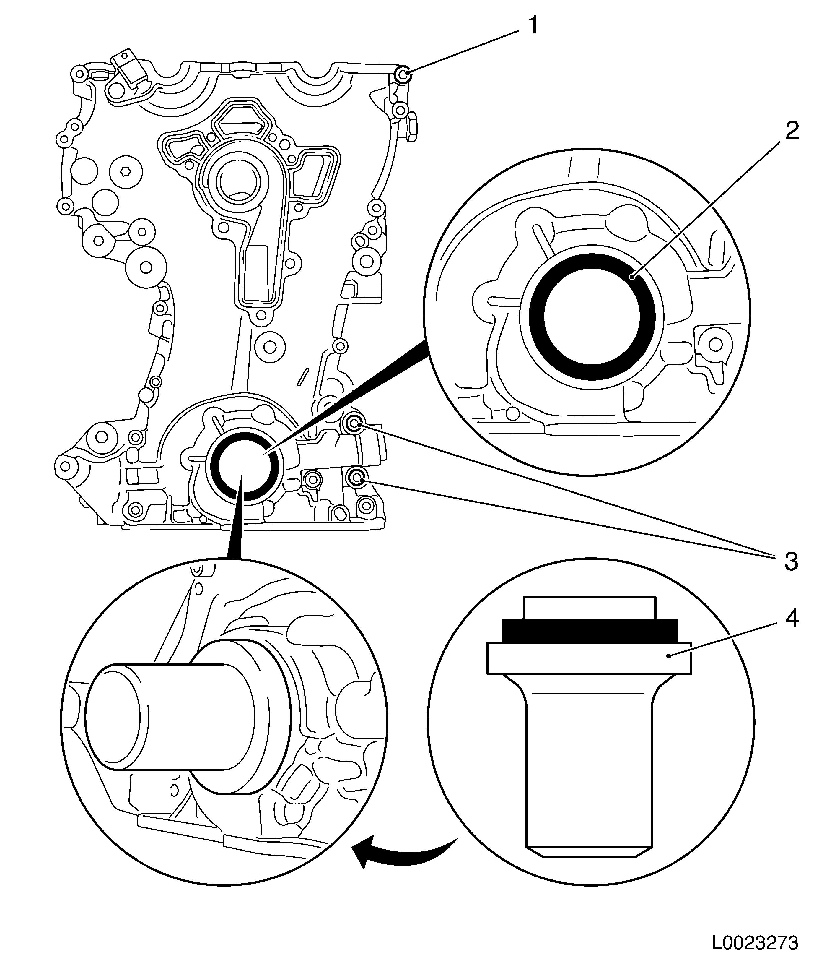
| 32. |
Remove timing case
| • |
Unscrew 15x bolts (arrows)
| – |
Do not damage camshaft sensor (1)
|
|
| • |
Prise out timing case seal ring
Note: Do not damage
sealing surface
|
|
|
|
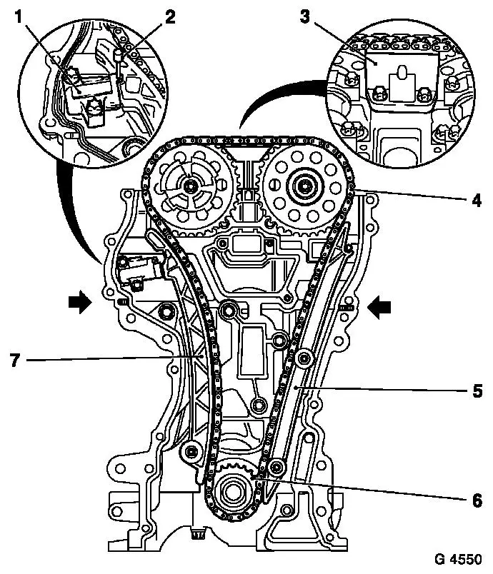
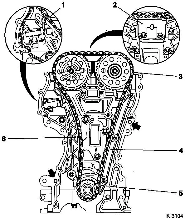
| 33. |
Detach chain drive
| • |
Slacken bolts, camshaft sprockets
| – |
Counterhold the camshafts on the hexagon
|
|
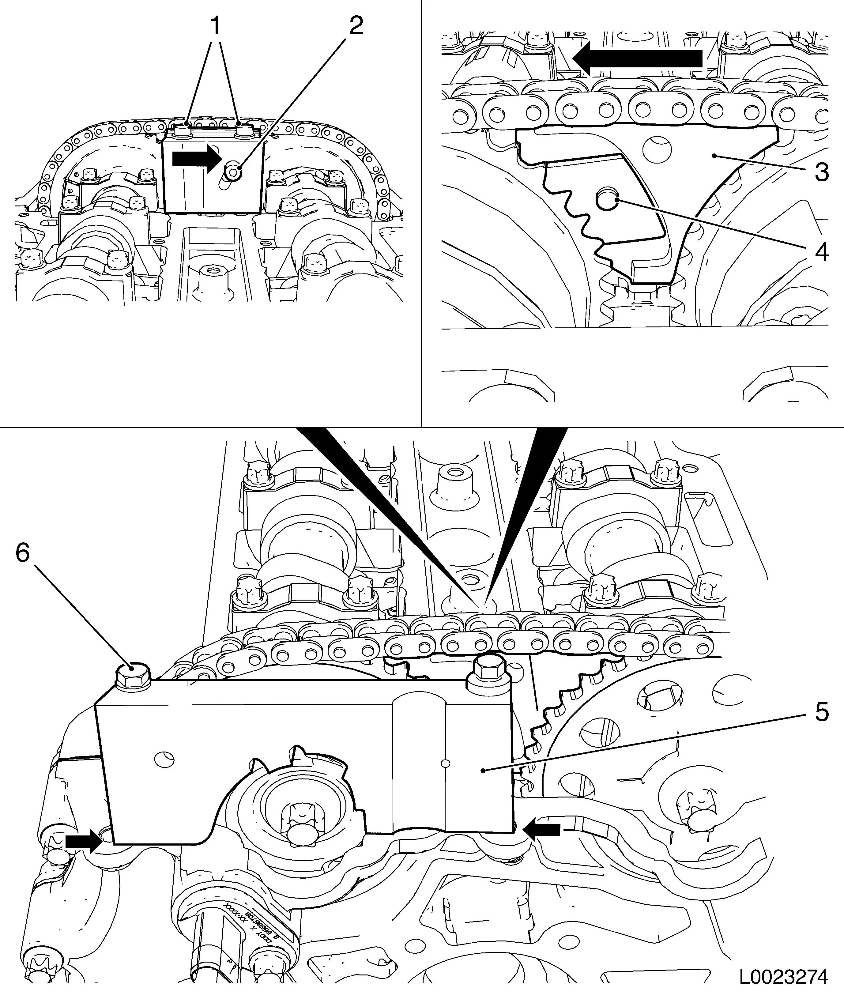
| • |
Lock chain tensioner (1)
|
| • |
Detach sliding rail (3), guide rail (5), tension rail (7),
camshaft sprockets
|
| • |
Take out timing chain (4) with drive gear (6)
|
| • |
Take out timing case gasket
|
|
|
| 34. |
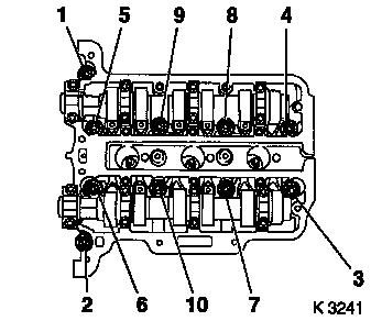
Remove cylinder head
| • |
Unscrew 10x cylinder head bolt
Note: Undo cylinder
head bolts in the order shown (1-10)
| – |
Release cylinder head bolts (90°)
|
| – |
Release cylinder head bolts (180°)
|
| – |
Remove cylinder head bolts
|
|
| • |
Place cylinder head on wooden blocks
|
| • |
Remove cylinder head gasket
|
|
|
|
| 36. |
Detach oil filter housing
|
| 37. |
Detach catalytic converter bracket
|
| 39. |
Detach crankshaft sensor
Note: Note seal
ring
|
| 40. |
Detach cylinder block from engine overhaul stand
| • |
Attach KM-2358
| – |
Attach 2x engine transport shackle to cylinder block
|
|
| • |
Hitch cylinder block up to workshop crane.
|
| • |
Lower cylinder block onto wooden pallet
|
| • |
Remove 2x engine transport shackle from cylinder block
|
|
 Install
| 41. |
Attach cylinder block to suitable engine overhaul stand
| • |
Attach KM-2358
| – |
Attach 2x engine transport shackle to cylinder block
|
|
| • |
Hitch cylinder block up to workshop crane.
|
| • |
Attach cylinder block to suitable engine overhaul stand
|
| • |
Detach 2x engine transport shackle
|
|
| 42. |
Input engine number, if required
|
| 43. |
Input 6x guide sleeve in cylinder block, if required
|
| 44. |
Clean all sealing surfaces
| • |
Cylinder block, cylinder head, cylinder head cover, oil filter
housing, crankshaft bearing bridge, timing case, oil pan, coolant
pump, exhaust manifold, intake manifold, cooling water
connector
|
|
| 45. |
Visually check components
| • |
Cylinder block, cylinder head, cylinder head cover, oil filter
housing, crankshaft bearing bridge, chain drive, timing case, oil
pan, coolant pump, exhaust manifold, intake manifold, cooling water
connecting piece
|
|
| 46. |
If testing and overhauling the cylinder head: Detach all
attachments from cylinder head
|
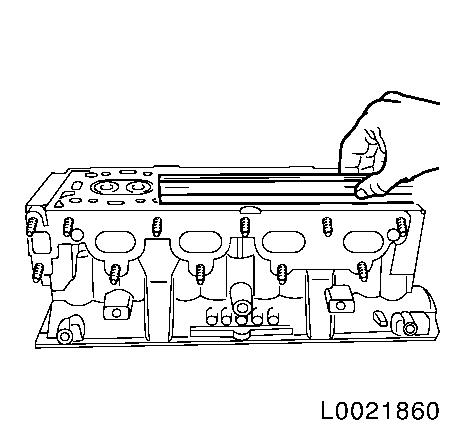
| 47. |
Using a straightedge, check cylinder block lengthways and
widthways for bend and in the diagonal for distortion.
Note: Before carrying
out the check, carefully clean the cylinder head sealing surface of
any old gasket residues. Do not use any metal, sharp-edged tools
when cleaning. Ensure that the cylinder head sealing surface is not
damaged.
|
|
|
|
| 48. |
Lock crankshaft
| • |
Unscrew crankshaft closure bolt
|
Important: It must be possible to
insert KM-952 smoothly and without major
effort into the crankshaft recess.
|
| • |
Insert KM-952 (1)
| – |
Rotate smoothly on crankshaft dihedral (2) in direction of
engine rotation until KM-952 engages
|
|
|
|
| 50. |
Attach crankshaft sensor
|
| 51. |
Attach catalytic converter bracket
|
| 52. |
Attach oil filter housing
| • |
Replace oil filter element
|
| • |
Attach oil filter housing cover
|
|
| 53. |
Adjust the camshafts
| • |
Insert KM-953-A (1)
| – |
Turn the camshafts by the hexagon
|
|
|
| 54. |
Adjust the camshafts
| • |
Insert KM-953-A
| – |
Turn the camshafts by the hexagon
|
|
|
| 55. |
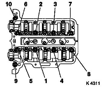
Attach cylinder head
| • |
Replace seal
Note: Marking TOP/OBEN
must point up
|
| • |
Replace cylinder head bolts
|
| • |
Align cylinder head to cylinder block with straightedge
|
| • |
Tighten 10x bolt 25 Nm+ 60° +
60° + 60°
Note: Note correct
tightening sequence (1-10)
|
|
|
|
|
| 56. |
Replace timing case gasket
| • |
Apply 2x sealing bead as shown (2 mm)
Note: After application
of the sealant, the chain drive and timing case must be fitted
within 10 minutes
|
| • |
Place new gasket in position
Note: Note guide
bushings (arrows)
|
|
| 57. |
Attach timing chain
| • |
Insert KM-953-A in camshafts
Note: If necessary,
gently adjust camshafts by the hex
|
| • |
Apply timing chain (3) together with drive gear (5)
|
|
| 58. |
Attach timing chain tension rail (6)
| • |
Tighten bolt 20 Nm
Note: Ensure correct
seat of timing chain
|
|
| 59. |
Attach timing chain guide rail (4)
| • |
Tighten 2x bolt 8 Nm
Note: Ensure correct
seat of timing chain
|
|
| 60. |
Attach timing chain sliding rail (2)
|
| 61. |
Relieve tension on chain tensioner
|
|
|
| 62. |
Attach timing case.
Note: Note guide
bushings and camshaft sensor
| • |
Tighten 13x bolt M6 (1) 8 Nm
|
| • |
Tighten 2x M10 bolt (3) 35 Nm
|
|
| 63. |
Replace front crankshaft sealing ring (2)
| • |
Drive in flush using KM-960
|
|
|
|
| 64. |
Fit torsional vibration damper (6)
| • |
Insert torsional vibration damper in oil pump rotor hex head
(2) and crankshaft dihedral (1)
Note: Marking on the
torsional vibration damper must align with the marking on the
timing case
|
| • |
Check for correct torsional vibration damper seating
| – |
Measure distance between torsional vibration damper and edge of
timing case (dimension a = 5,5 mm)
|
|
| • |
Screw in torsional vibration damper bolt (7)
|
| • |
Tighten torsional vibration damper bolt 150 Nm
| – |
Counterhold it with EN-49979 (4)
together with KM-956-1 (5)
|
|
|
|
| 65. |
Fix 2x camshaft sprocket
| • |
Attach EN-49977-200 (3)
Note: Press EN-49977-200 in direction of arrow so that the
teeth (4) engage in the teeth of the intake camshaft sprocket
without play
| – |
Tighten 2x fastening bolt (1)
|
| – |
Tighten adjusting bolt (2)
Note: Press EN-49977-200 in direction of arrow when
tightening
|
|
|
| 66. |
Adjust and fix phase sensor disc
| • |
Rotate phase sensor disc until EN-49978 (5) can be inserted
Note: EN-49978 must rest on the surfaces shown (arrows)
without play
|
| • |
Tighten 2x fastening bolt (6)
|
|
| 67. |
Tighten 2x camshaft sprocket 50 Nm +
60°
| • |
Counterhold with open-end wrench against the hexagon of the
camshafts
|
|
| 68. |
Remove all special tools: KM-952 ,
EN-953 , EN-49977-200 , EN-49978
|
|
|
| 70. |
Repeat adjustment procedure if necessary
|
| 71. |
Remove locking tool
| • |
KM-952 , KM-953-A , EN-49978
|
|
| 72. |
Insert crankshaft sealing plug and tighten 50 Nm
Note: Use new seal
ring
|
| 73. |
Attach coolant pump together with thermostat housing
| • |
Insert 9x bolt 8 Nm
Note: Note different
bolt lengths
|
|
| 74. |
Attach coolant pump belt pulley
| • |
Insert 3x bolt and tighten 22 Nm
Note: Counterhold with
open-end wrench on flange
|
|
| 75. |
Rotate engine on engine overhaul stand through 180°
|
| 76. |
Attach oil baffle plate
|
|
| 77. |
67. Install oil pan
| • |
Apply sealant (dimension I = 2 mm)
Note: Oil pan
installation must take place within 10 minutes
| – |
For the bolt hole shown
|
|
| • |
Rotate 2x EN-49980 (1) into the
positions shown
|
Important: When positioning the
oil pan, it is necessary to ensure that the sealing bead is not
wiped away.
|
| • |
Carefully apply the oil pan
Note: Pass EN-49980 through corresponding bolt holes
|
| • |
Insert 4x bolt, offset diagonally
|
| • |
Adjust oil pan with rubber mallet and straightedge
Note: Straightedge must
rest on the oil pan and cylinder block without play
|
|
|
| 78. |
Rotate engine on engine overhaul stand through 180°
|
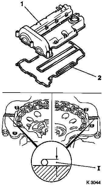
| 79. |
Attach cylinder head cover (1)
| • |
Replace gasket (2), seal rings
|
| • |
Apply sealant (dimension I = 2 mm)
Note: Complete assembly
work within 10 minutes
|
| • |
Attach engine vent hose
|
|
| 80. |
Attach ignition module
|
|
|
| 81. |
Install EGR valve
Note: Use new seal
|
| 82. |
Attach coolant hoses
| • |
to exhaust gas recirculation valve
|
|
| 83. |
Attach intake manifold
| • |
Attach EGR pipe to EGR valve
Note: Use new seal
|
| • |
Attach engine vent hose to cylinder head cover
|
|
| 84. |
Install exhaust manifold
| • |
Attach 2x bolt to catalytic converter bracket
|
| • |
Tighten 7x exhaust manifold nut 22
Nm
|
| • |
Tighten 2x catalytic converter bracket bolt 10 Nm
|
|
| 85. |
Install heat shield
| • |
Clip in oxygen sensor mixture regulator wiring harness plug
|
|
| 86. |
Install dipstick guide tube
|
| 88. |
Attach engine management wiring harness
| • |
Connect 11x wiring harness plugs
|
| • |
Attach earth cable, engine control unit
|
|
| 90. |
Install alternator
| • |
Tighten 2x screwed joint 35 Nm
|
|
| 91. |
Attach engine wiring harness
| • |
Attach alternator wiring harness
|
| • |
Fasten starter wiring harness
|
|
| 92. |
Attach ribbed V-belt tensioner -
| • |
Tighten bolt (M8) 20 Nm
|
| • |
Tighten bolt (M10) 55 Nm
|
|
| 93. |
Insert ribbed V-belt
Note: Ensure correct
running direction and installation position
| • |
Release ribbed V-belt tensioner
|
|
| 94. |
Attach engine bracket right
|
| 95. |
Top up engine oil.
| • |
Observe specified engine oil quantity
|
|
| 96. |
Detach engine from engine overhaul stand
| • |
Attach KM-2358 to 3x engine transport
shackle
|
| • |
Hitch engine up to workshop crane.
|
| • |
Lower engine onto wooden pallet
|
| • |
Detach KM-2358 from 3x engine
transport shackle
|
|
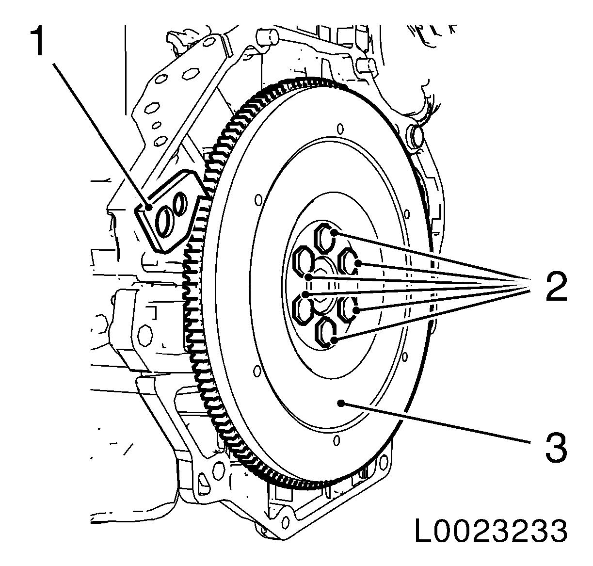
| 97. |
Fit flywheel
| • |
Clean 6x thread in crankshaft
|
| • |
Tighten 6x new bolt 35 Nm +60
°
|
|
| 98. |
Attach thrust plate and clutch disk
|
| 99. |
Attach manual transmission to engine
|
|
