|
Remove and install manual transmission (Z13DTH/M20
MTA)
Note: Follow
Easytronic safety notes .
If the transmission is replaced, the following parts must be
transferred:
| 1. |
Left engine damping block retaining bracket |
| 2. |
MTA system |
 Remove Remove
| 2. |
Remove top engine cover
|
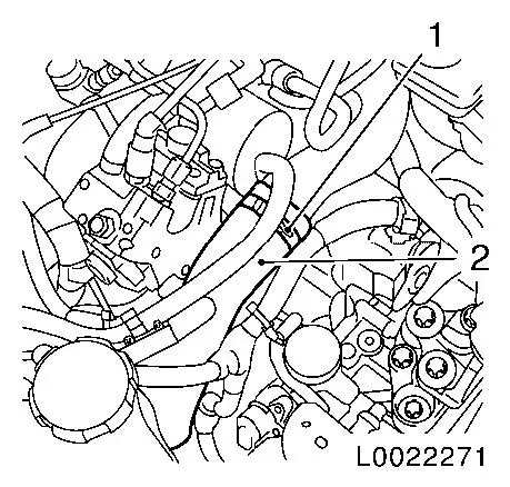
| 3. |
Pull off top charge air hose (2)
|
|
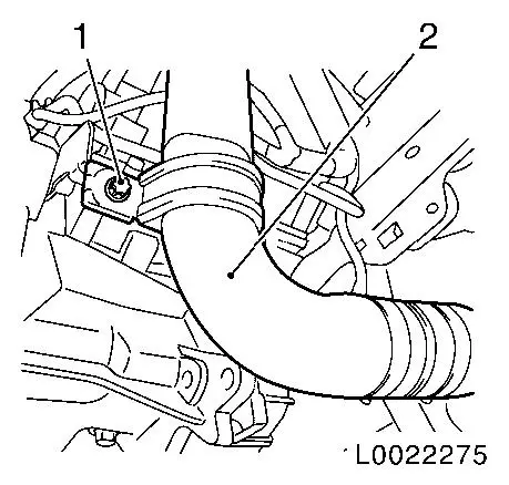
|
| 4. |
Remove coolant expansion tank
| • |
Unclip tank and lay aside
|
|
|
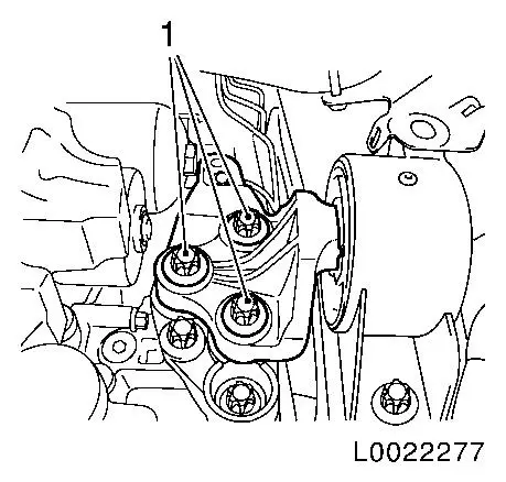
|
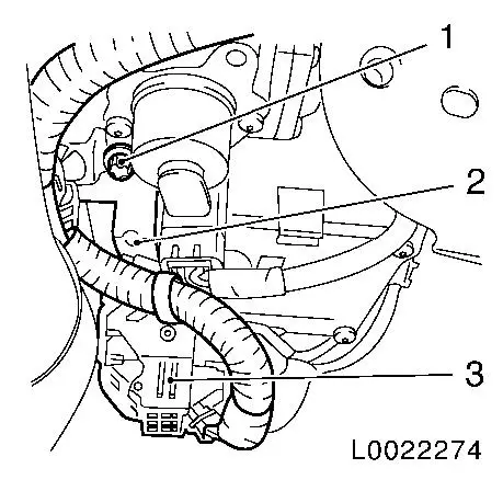
| 5. |
Detach supply unit for MTA system
| • |
Unscrew 3x bolts (1)
Note: Note different
bolt lengths
|
|
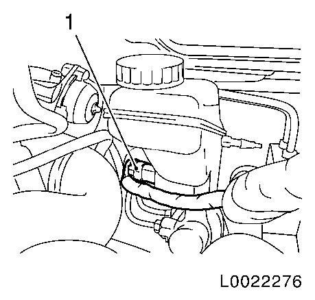
|
|
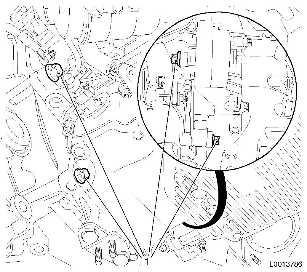
| 6. |
Detach holder for high pressure line MTA system (1)
|
|
|
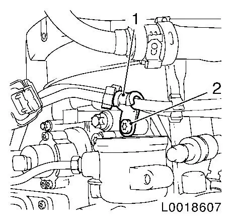
| 7. |
Detach MTA system wiring harness plug
| • |
Unlock and separate wiring harness plug (3) at TCU
|
| • |
Detach wiring harness bracket (2)
|
|
|
|
| 8. |
Drain off transmission fluid
Note: Place collecting
pan underneath.
| • |
Unscrew drain bolt
Note: Allow
transmission fluid to drain out for approx. 10 minutes.
|
| • |
Tighten new drain bolt 20 Nm
|
|
| 9. |
Remove front axle body
|
| 10. |
Detach charge air hose (2) from bracket
|
|
|
| 11. |
Detach right axle shaft
| • |
Attach axle shaft to vehicle underbody
|
|
| 12. |
Detach left axle shaft
| • |
Attach axle shaft to vehicle underbody
|
|
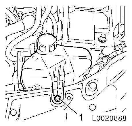
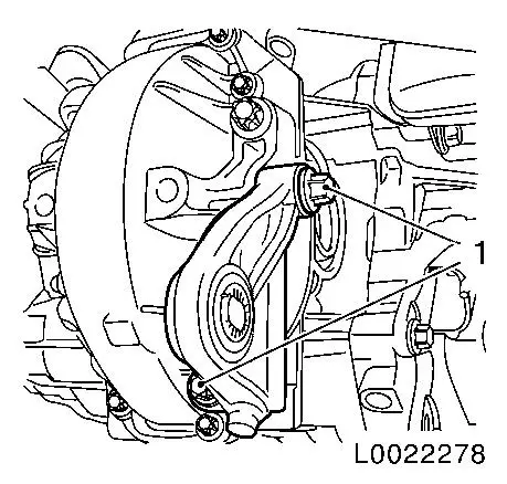
| 13. |
Unlock and separate brake fluid level sensor wiring harness
plug (1)
| • |
Unclip wiring harness plug
|
|
|
|
| 15. |
Detach transmission from left engine damping block
|
| 16. |
Lower engine with transmission on EN
47650 by approx. 20 cm
Note: Ensure that the
coolant hoses and wiring harnesses are not stretched.
Do not damage wiring harnesses and attaching parts
Be careful of vacuum line on throttle valve module
|
|
|
|
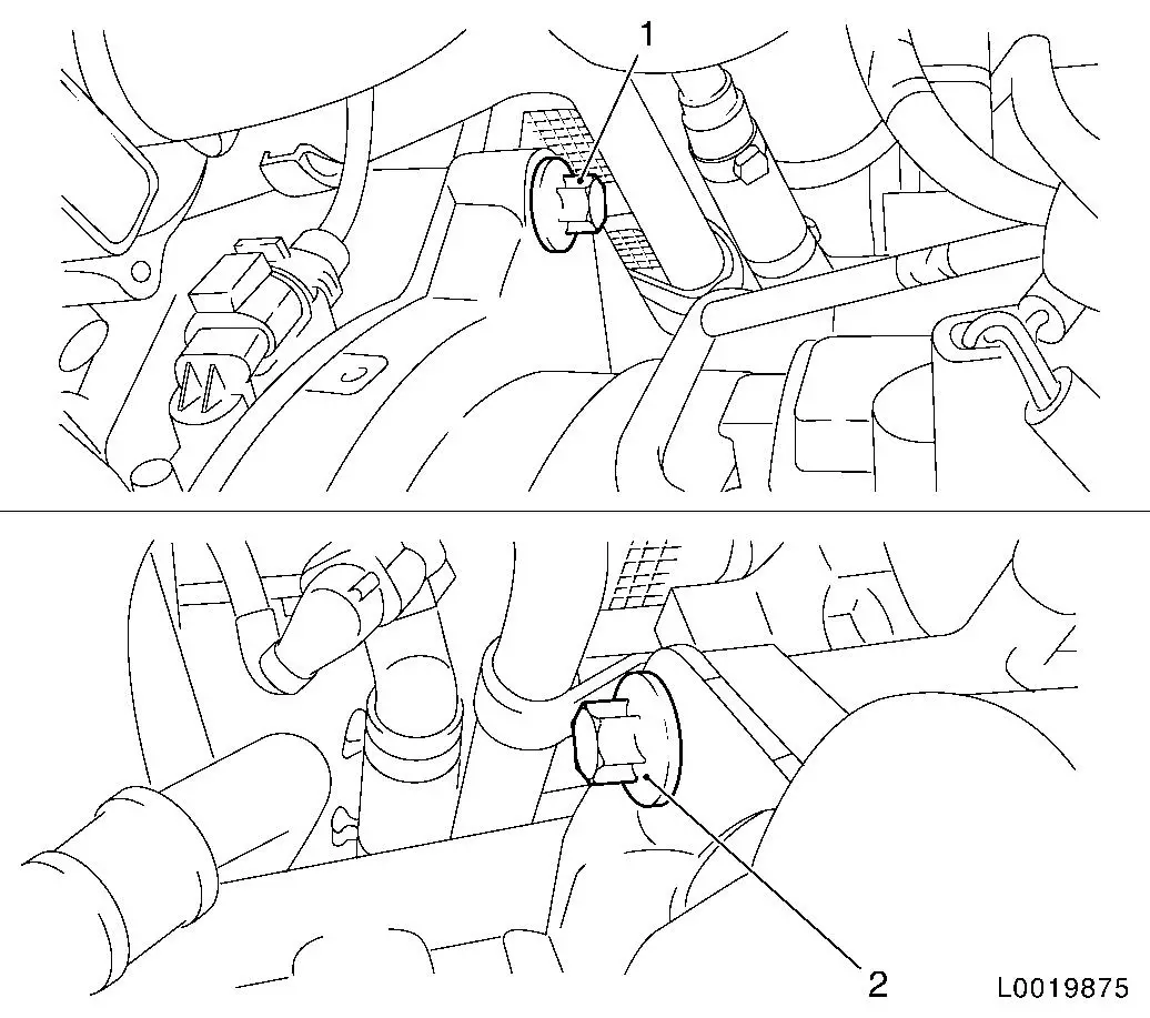
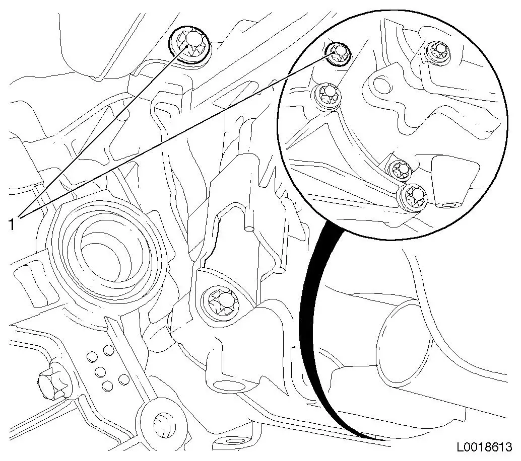
| 18. |
Release transmission at top
Note: With the vehicle
raised, release the upper gearbox bolts from below.
| • |
Unscrew front (1) and rear (2) upper gearbox bolts
|
|
|
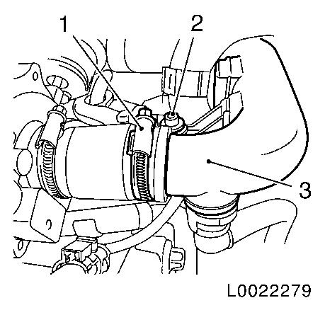
| 19. |
Detach intake pipe (3) from turbocharger
| • |
Unscrew bolt (2) on holder
|
|
|
|
| 20. |
Remove rear engine damping block
|
|
|
|
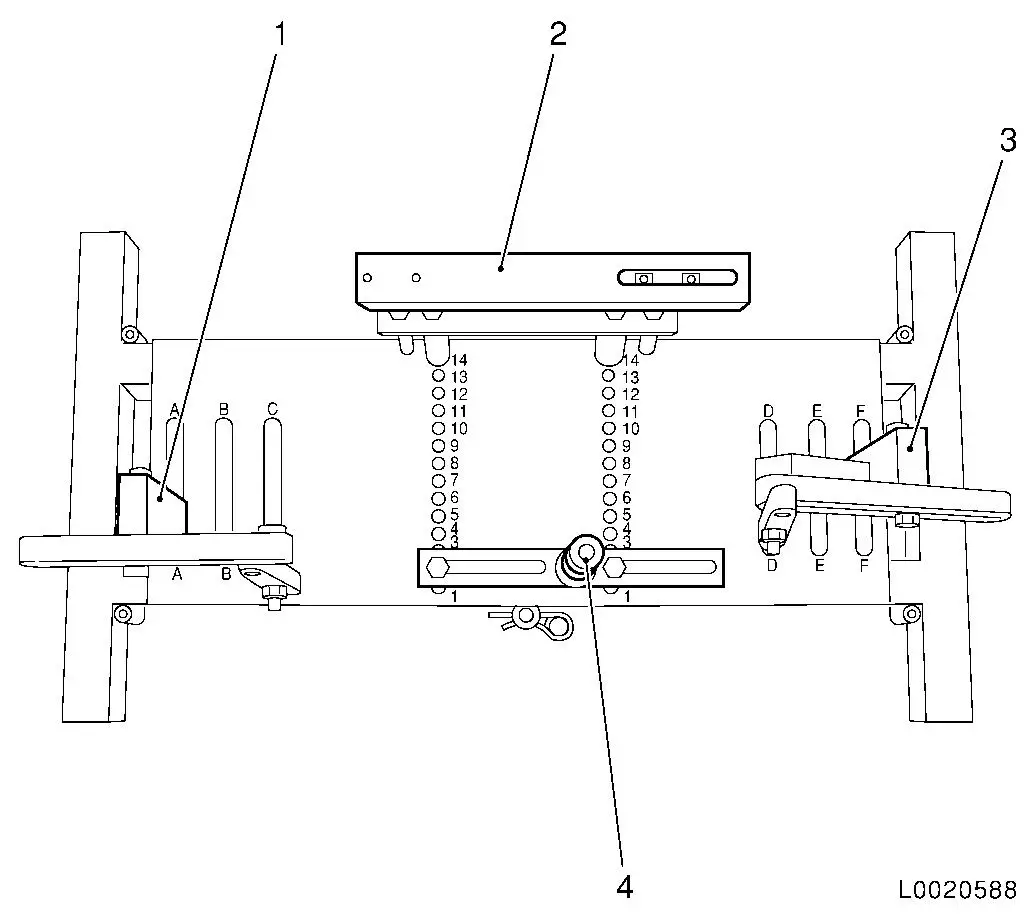
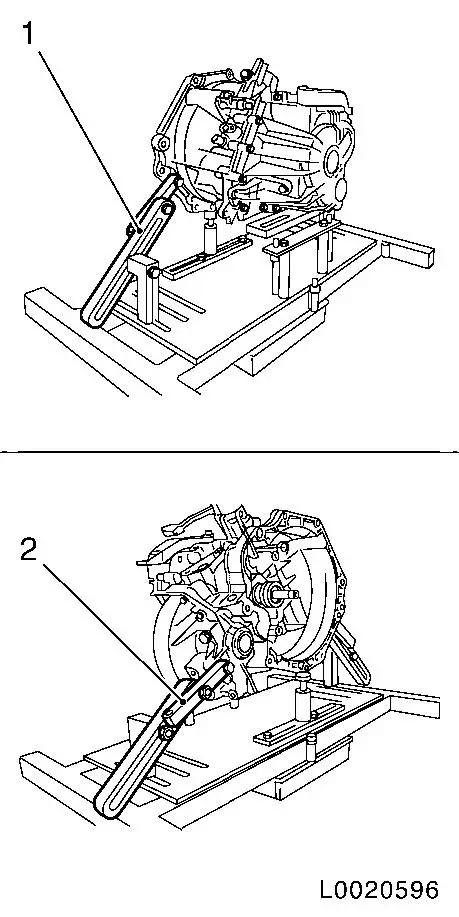
| 21. |
Place transmission fixture DT-47648
on KM-904 and assemble as shown in
illustration:
|
Component
|
Position on base plate
|
Designation
|
|
DT-47648-2
(4)
|
2
|
Clutch housing support
|
|
DT-47648-3
(2)
|
14
|
Transmission housing support
|
|
DT-47648-5 left
(1)
|
A
|
Rear transmission support with pivot arm
|
|
DT-47648-5 right
(3)
|
F
|
Front transmission support with pivot arm
|
|
|
Important: Pay strict attention
to manufacturer's notice for transmission fixture DT-47648 .
|
| 22. |
Attach DT-47648 to transmission
Note: Loosen all screw
connections of the swivel arms and supports to the base plate
before placing them under load. Rotate the supports as far down as
possible by way of the spindles.
| • |
Place DT-47648 with supports beneath
the transmission
|
| • |
Tighten screw connections on the supports
|
| • |
Attach pivot arms (1) and (2) to transmission
|
| • |
Tighten the screw connections of the pivot arms starting from
the transmission to the base plate
Note: Align the swivel
arms so that as a little lever force as possible is created.
|
|
|
|
|
| 23. |
Removing transmission
| • |
Press the engine away from the transmission and slowly lower
the hydraulic jack
Note: Do not damage
wiring harnesses and attaching parts
|
|
|
Important: Do not damage
attaching parts when putting the transmission down.
|
| 24. |
Detach gearbox from transmission holder DT-47648
Note: A second person
is required.
| • |
Put transmission down carefully
|
|
 Install
| 25. |
Attach gearbox to transmission holder DT-47648
Note: A second person
is required.
|
| 26. |
Install transmission using DT-47648
| • |
Raise transmission and align it
|
| • |
Place transmission so that it is in even contact with the
engine
Note: Ensure it is
seated perfectly.
|
|
|
| 27. |
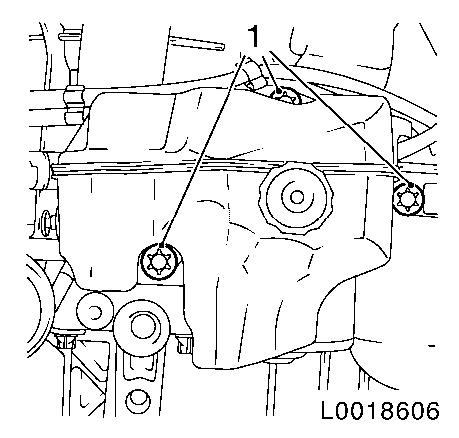
Fasten transmission at the bottom
| • |
Tighten 2x M12 bolts (1)
|
|
|
| 28. |
Detach transmission fixture DT-47648
from transmission
| • |
Lower hydraulic jack with transmission fixture DT-47648 and remove
|
|
|
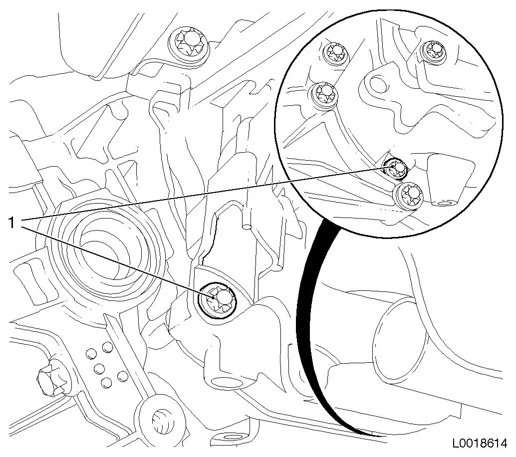
| 29. |
Fasten transmission at the bottom
| • |
Tighten 2x bolt M10 (1) 40 Nm
Note: Note different
bolt lengths
|
|
|
|
| 30. |
Fasten transmission at the top
Note: With the vehicle
raised, attach the upper gearbox bolts from below.
| • |
Tighten front (1) and rear (2) upper gearbox bolts M12 60 Nm
|
|
|
| 31. |
Attach intake pipe (3) to turbocharger
| • |
Tighten bolt (2) on holder
|
|
|
|
| 32. |
Install rear engine damping block
| • |
Tighten 2x bolts (1) 80 Nm +
45°
|
|
|
|
Important: Do not damage wiring
harnesses and attaching parts
Be careful of vacuum line on throttle valve module
|
| 33. |
Raise engine and transmission on the left hand side
|
| 34. |
Attach transmission to left hand engine damping block
| • |
Tighten 3x bolts (1) 55 Nm
|
|
|
|
| 36. |
Connect wiring harness plug (1) for brake fluid level sensor
and lock
|
|
|
| 37. |
Attach charge air hose (2) to bracket
|
|
|
| 38. |
Attach left axle shaft
|
| 39. |
Attach right axle shaft
|
| 40. |
Install front axle body
|
| 41. |
Attach MTA system wiring harness
| • |
Connect wiring harness plug (3) to TCU and lock
|
| • |
Attach wiring harness bracket (2)
|
|
|
|
| 42. |
Attach holder for high pressure line MTA system (1)
|
|
|
| 43. |
Attach supply unit for MTA system
| • |
Tighten 3x bolts (1) 10 Nm
Note: Note different
bolt lengths
|
|
|
|
| 44. |
Attach coolant expansion tank
|
|
|
| 45. |
Connect top charge air hose (2)
|
|
|
| 46. |
Attach top engine cover
|
| 47. |
Top up with transmission fluid 
|
| 48. |
Install battery
| • |
Install battery support
|
|
| 49. |
Program volatile memories
|
| 50. |
Programming the MTA system
|
| 51. |
Necessary commissioning routines for Easytronic
|
| 52. |
Work to be performed with Tech 2
|
|
