Field Remedy: 2313
| Subject: |
Engine compartment electronics module -
Water ingress |
| Models: |
Engines: |
Option: |
| Corsa-D 2008... |
All |
|
| Complaint: |
Bad or no engine running / MIL-Lamp on /
Several electrical malfunctions / Discharged battery. |
| Cause: |
Water ingress in engine compartment
electronics module. |
| Production: |
Modified parts have been introduced in
production as of VIN W0L0SDL0886089257 (plant Eisenach), VIN
W0L0SDL0884266553 (plant Zaragoza). |
Remedy:
In case of customer complaint the electric connectors in the engine
compartment electronics module have to be checked for corrosion and
if necessary restored. Additional sealing operations have to be
carried out as well.
Working procedure:
1. Open bonnet.
2. Disconnect battery.
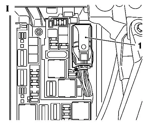
3. Detach cover engine compartment electronics module.
4. Disconnect connector (1) and pull it off upwards (picture I).
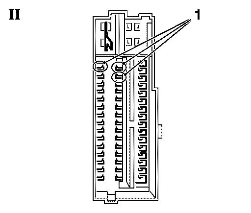
5. Check connector pins for corrosion (picture II)
    - If connector pins and crimps show indication of corrosion, they
      have to be removed from the connector terminal, cleaned and
      again applied into the connector. Removing and installing of the
      connector pins is mentioned below beginning with step 7.
    - If contact areas of the connector pins are already damaged by
      corrosion they have to be replaced. The working procedure is
      mentioned below beginning with step 6.
      Note:
      Maximum 6 connector pins are allowed to be replaced. If more
      than 6 connector pins are damaged the front and the rear body
      wiring harness have to be replaced.
      Note:
      Connector pin number 16, 33 and 34 (1) belong to the
      Airbag-System. If one of these connector pins shows corrosion
      the front and the rear body wiring harness have to be replaced
      as well.
      Note:
      If the front and the rear body wiring harness have to replaced,
      the accordant wiring harness code has to be observed.
      Identification of wiring harness can be carried out by a label
      on the wiring harness behind the left service lid in the luggage
      compartment or by means of Tech 2 in the Body-Control-Module.
6. Remove wind protection panel
    - see working procedure "Replace wind protection panelling",
      group "A", Service-Instruction Corsa-D.
      (Document number 01501230)
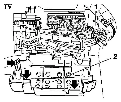
 7. Remove connector inset from engine compartment electronics
    module (picture III)
    - Unscrew 1x nut (1)
    - Unlock 3x latch (arrows) with screwdriver
    - Detach connector inset (2) upwards and slew it clockwise
      to the side.

8. Open connector inset (picture IV)
    - Unlock cover (2) on the bottom of connector inset 3x (arrows)
      and detach
    - Remove 3x cable strap (1).
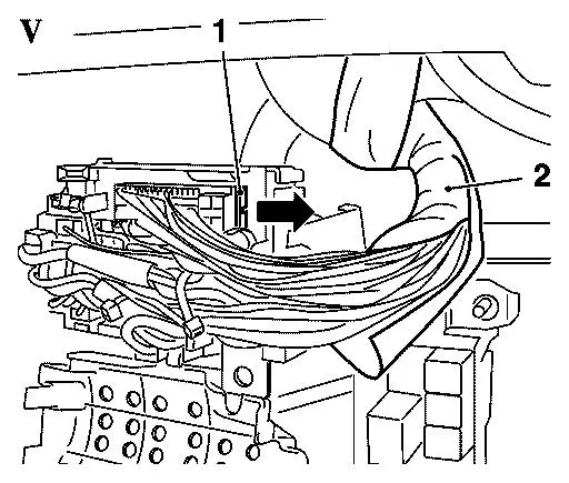
9. Unlock locking comb connector locking (picture V)
    - Pull locking comb (1) with screwdriver into direction of the
      arrow
    - Split wiring harness isolation (2) about 10 cm and cut it off.
10. Eject damaged connector pin with special tool MKM-923-1 from
    connector.
11. Cut ejected cable direct behind connector pin and bare wire
    about 3 mm.
    Note:
    If corrosion has advanced up to the copper cable cut accordingly
    longer.
12. Bare repair cable about 3 mm.
13. Shorten shrinkable tubing to a length of about 30 mm.
14. Connect repair cable and ejected cable with connecting sleeve
    Note:
    Push up shrinkable tubing before.
15. Push shrinkable tubing over connecting point and it heat up
    with a hot air blower until hotmelt adhesive escapes even.
    Note:
    Avoid damages to the other cables by heat.
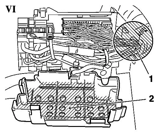
16. Plug connector pin into connector in its original position.
    Note:
    Step 10. till 16. have to be carried out for all damaged connector
    pins maximum 6 pieces). Attend for offset of the several
    connecting points. Connecting points have to be located only in
    the hatched area (2, picture VI). In area (1) no connecting points
    are allowed to be located.
    Note:
    The valid instructions for the repair of wiring harnesses
    have to be observed, quod vide "Safety regulations of electrics/
    electronics", group "N", Service-Instruction Corsa-D
    (Document number 00026357).
17. Insert locking comb connector pins and lock it.
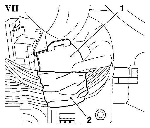
18. Seal wiring harness (picture VII)
    - Take off the half amount of the seal plasticine (2) from the
      repair kit and knead it between the cables in the area of the
      wiring harness stabiliser (1).
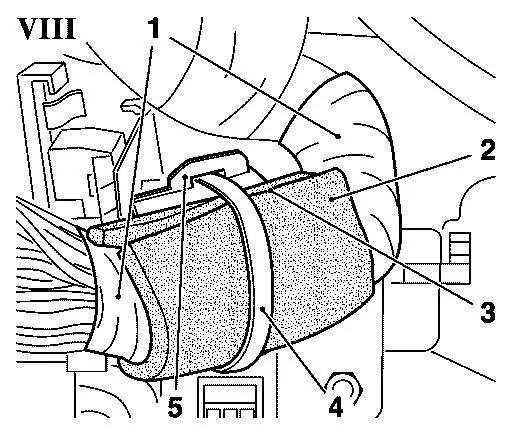
19. Isolate wiring harness (picture VIII)
    - Laminate bared area of wiring harness with insulation tape (1)
      completely
      Note:
      To ensure a better distribution of seal plasticine inside
      attract insulation tape solid.
      Note:
      Use PVC-Tape, no textile tape.
    - Affix self-adhesive sponge rubber mat (2) as shown onto wiring
      harness
      Note:
      Beginnings (3) have to show upwards.
    - Insert caple strap (4) into wiring harness stabiliser (5) and
      tighten.
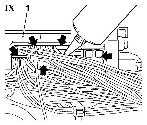
20. Seal underside of plug connection front body wiring harness
    with special grease
    - Fill all cells of plug connection (1, picture IX) front body
      wiring harness from the underside completely with special grease
      (P/N 09163339 - arrows).
21. Close connector inset
    - Attach 2x cable strap and tighten
    - Close cover until latches clip in.
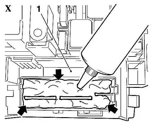
22. Seal upper side of plug connection front body wiring harness
    with special grease
    - Fill cell on upper side of plug connection (1, picture X) with
      special grease (P/N 09163339 - arrows) until all connector pins
      are covered completely.
    Note:
    During working with special grease, take care that no other areas
    get in contact with the special grease as the sealing compound
    will not adhere on areas already coated.
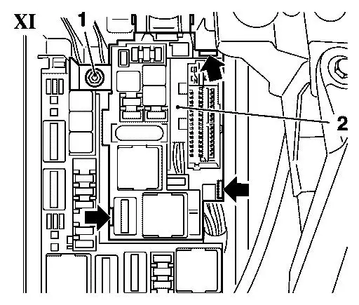
23. Install connector inset into engine compartment electronics
    module (picture XI)
- Insert connector inset (2)
      Note:
      Latches (3x) have to clip in audible.
    - Screw in 1x nut (1) and tighten 8 Nm
    - Check all components in electronics module for proper mounting.
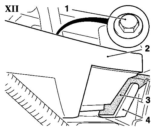
24. Seal bulkhead closing part below wind protection panel with
    foam seals (picture XII)
    - Unscrew screw (1) from bulkhead closing part (2)
    - Lift bulkhead closing part and affix self-adhesive foam seal
      strip (3) as shown
    - Attach self-adhesive washer onto screw (1) and pull off adhesive
      protective foil
      Note:
      Adhesive side has to show away from screw head.
- Screw in screw and tighten
      Note:
      Attend not to damage self-adhesive washer through tightening.
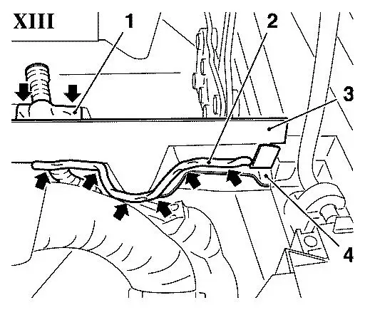
25. Seal bulkhead closing part below wind protection panel with
    compound glueing seal (picture XIII)
    - Apply compound glueing seal (P/N 90485251 - arrows) in the
      area (1) of the opening for washer-fluid hose (arrows)
      Note:
      Seal opening on upper and lower side.
    - Apply compound glueing seal (P/N 90485251 - arrows) in the
      area (2) between bulkhead closing part (3) and body (4).
      Note:
      Before application of compound glueing seal fit wind protection
      panel slackly and connect flanges of washer-fluid hose.
      Washer-fluid       hose must be positioned as shown behind the
      wiring harness.
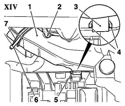
26. Install water protection cover (picture XIV)
- Install water protection cover (1) as shown
      Note:
      Washer-fluid hose (2) must run in designated guide.
    - Attach fixing tab (3) on side panel (5) of electronics
      module
      Note:
      Fixing tab (3) must be located between guides (4) of
      electronics module.
- Affix cover to wiring harness with cable strap (6)
      Note:
      Cable strap must run between guides (7).
- Attach cover electronics module until latches clip in audibly.
27. Install wind protection panel
    - see working procedure "Replace wind protection panelling",
      group "A", Service-Instruction Corsa-D.
      (Document number 01501230)
28. Connect battery.
29. Close bonnet.
30. Program volatile memory.
Spare-Parts: Part-No.: Catalogue-No.:
Repair kit                              13301544       90 12 277
Shrinkable tubing                       90543875       12 86 666
Connecting sleeve                       90543865       12 86 663
Cable strap                             90039907       12 88 900
Compound glueing seal                   90485251       15 03 295
Washer self-adhesive                    90184910       05 60 768
Special grease                          09163339       19 48 877
Labour Times: TC: Hours:
U3 231 30 Sealing wiring harness 90 1,1
The costs for this repair will be covered during the normal warranty.
The regular warranty procedure will apply.
| FunctionalGroup: |
N - Electrical Equipment |
| Complaint Group: |
04 - Electrical failures |
| Trouble Code: |
P1120,P2121,B2580,other |
|
