Nova
|
Alternator, Check
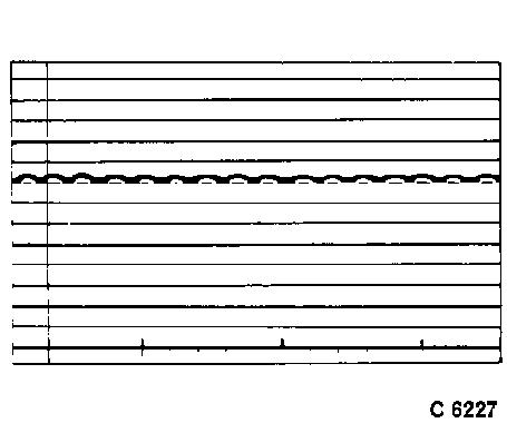
Checking can be carried out both in installed condition and on a test stand. In the following, checking in installed condition is described, checking on a test stand is carried out analogously. Use a suitable oscilloscope to simultaneously evaluate electronic components.
A fully charged battery is required for checking.
In order to avoid defects, the following safety measures must be observed:
1. Negative terminals of battery and alternator must correspond.
2. Never run alternator on an uncontrolled open circuit.
3. Never short-circuit clamps on alternator.
4. Do not reverse alternator polarity.
5. If an auxiliary battery is connected (e.g. as starting aid), always ensure that identical battery terminals are connected to one another.
6. When connecting a charging unit, connect charger lines to correct battery terminals. Disconnect ground lead from battery during charging.
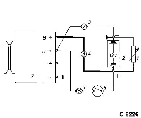
Disconnect battery. Disconnect red connecting lead from alternator terminal "B +"
Insert ammeter (measuring range 100 A) in disconnected lead. Connect battery.
Connect variable load resistor to battery terminals. Before connecting, set resistance to "0". Connect lead first to battery, then to resistor. Do not short circuit battery with resistor (1).
Connect wheel speed sensor. Connect oscilloscope according to manufacturer's instructions.
Start engine. Read off current and voltage at different engine speeds.
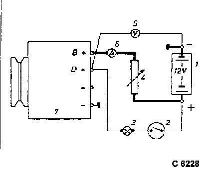
Bosch Alternator Connect tachometer, load resistor and voltmeter/ammeter according to manufacturer's instructions. Disconnect ground cable from battery. Disconnect red lead from alternator terminal "B +" Connect ammeter (measuring range 100 A) between disconnected red cable and terminal "B +".
Connect resistor in series with battery. Connect ground cable to battery.
Delco-Remy Alternator Connect tachometer, load resistor and voltmeter/ammeter as in performance test.
Checking Procedure:
Start engine.
Bosch Alternator: Adjust load resistance, until ammeter indicates prescribed value. Read off regulated voltage at adjusted test load. For test values see Technical Data.
Delco-Remy Alternator: Adjust load resistance to half nominal value and read off regulated voltage. For test values see Technical Data.
Important:
Test alternator only with fully-charged battery, connected in parallel. Do not disconnect load resistor and battery until alternator comes to standstill.
Reason: Disconnection of the load without battery in parallel - even for the shortest time -generates voltage transients, which can destroy the alternator diodes.
|
||||||