|
Windscreen, Remove and Install or Replace - F69,
F35 with BO-46974
Note: This document
describes the removal of the windscreen glass using the Glass
Removal System BO-46974 . Individual
steps in the operation for non-destructive removal of the
windscreen are described as an addition to the existing video VT
54.
Warning: To avoid
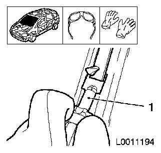
injuries to the hand and eye area, always put on gloves and goggles
from the Tool Kit BO-46974 before
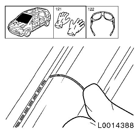
starting work.
The Tool BO-46974 is recommended for
non-destructive removal of the glass. You will find further
information in the video VT 54.
Note: Park vehicle on
a flat surface and move front wheels to the straight ahead
position.
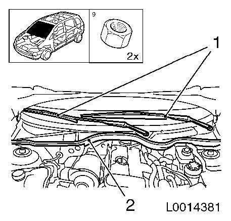
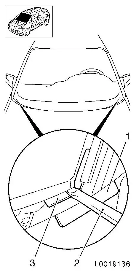
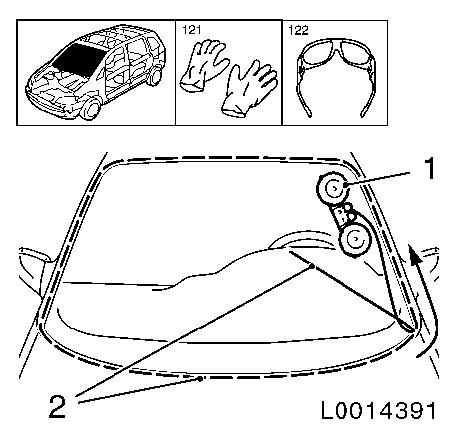
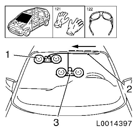
 Remove Remove
| 1. |
Detach windscreen wiper arms (1)
|
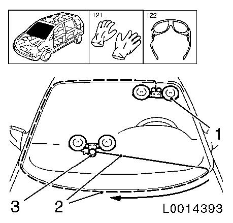
| 2. |
Detach rubber seal (2), water deflector
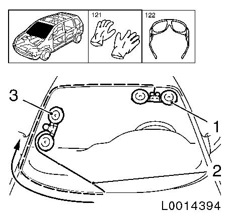
|
|
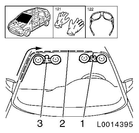
|
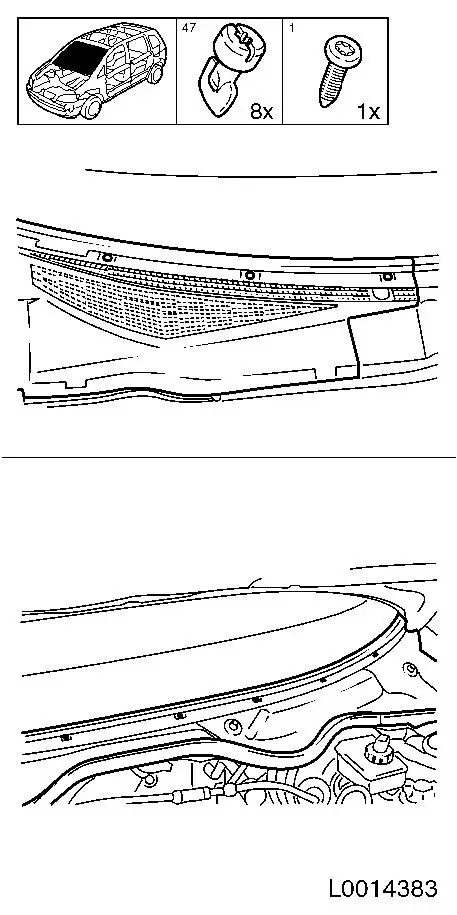
| 3. |
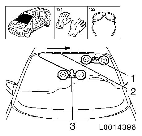
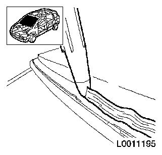
Detach lower windscreen trim strip
| • |
Detach windscreen trim strip with a suitable tool
|
|
|
|
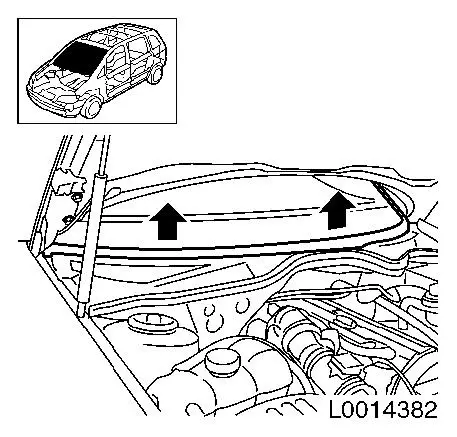
| 4. |
Detach water deflector (right side)
| • |
Unscrew and remove 3x quick-release fitting
|
|
| 5. |
Detach water deflector (left side)
| • |
Unscrew and remove 5x quick-release fitting
|
|
|
|
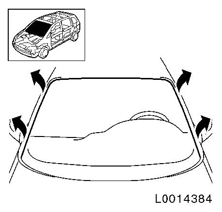
| 6. |
Detach windscreen trim strip around the circumference
| • |
Remove with plastic wedge
|
|
|
|
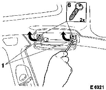
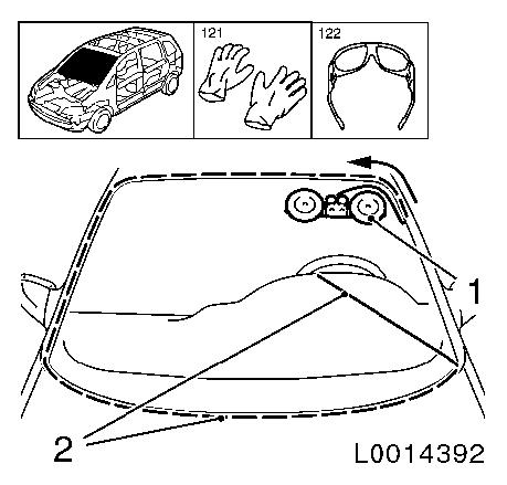
| 7. |
For model year 2000, the windscreen trim strip was installed
with retaining clamps on the lower left and right-hand sides.
Note: Mask off the wing
to prevent damage (1).
| • |
Carefully prise 2x clamps (3) out of the bed of adhesive using
a suitable tool (2)
|
|
|
|
| 8. |
Detach interior rear view mirror
| • |
Pull away interior rear view mirror forwards
|
|
| 9. |
For vehicles with rain sensor:
| • |
Unclip rain sensor cover
|
| • |
Unclip rain sensor and remove
|
| • |
Disconnect wiring harness plug, rain sensor
|
|
| 10. |
Detach both inner panelling sections, upper A-pillar
| • |
Prise out 4x covering panels (1), handle
|
| • |
Detach 2x A-pillar upper inner panelling
|
|
|
|
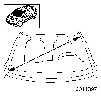
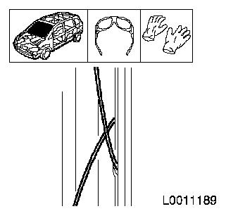
| 11. |
Measure windscreen diagonals
| • |
Cut off the cutting wire to four times the length, approx 5900 mm
Note: The circumference
of the relevant roll of wire is approx. 1 metre.
|
|
|
|
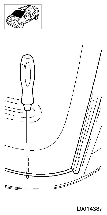
| 12. |
Heat awl with a suitable tool
|
| 13. |
Push awl through bed of adhesive in the area of the front
bulkhead
Note: Ensure that the
windscreen is not damaged as otherwise stress cracks may occur in
the windscreen.
|
|
|
| 14. |
Insert wire
| • |
Thread cutting wire into the bore in the awl and bend over
|
| • |
Draw cutting wire into the interior of the vehicle as far as
the centre of the steering wheel with the pointed awl
|
|
|
|
| 15. |
Lay wire around the circumference under the windscreen
Note: Insert the
cutting wire under the mounting strip and under the windscreen in
the lower left and right-hand area.
|
| 16. |
Heat awl with a suitable tool
|
| 17. |
Pull in the second end of the wire
| • |
Push pointed awl through the bed of adhesive overlapping the
first entry point by approx. 1 cm
|
| • |
Thread cutting wire into the bore in the awl and bend over
| – |
Draw the rest of the wire into the interior with the pointed
awl
|
|
|
|
|
| 18. |
Position seat
| • |
Position driver's seat in such a way that the entire windscreen
can be reached with the winch
|
|
| 19. |
Position the winch with two reels in the vehicle
| • |
Position winch (1) in the upper left area of the A-pillar
|
| • |
Attach cutting wire (2) to winch
Note: Ensure the
cutting wire is laid correctly around the pulley of the winch
| – |
Insert ratchet and apply tension to the cutting wire
|
|
|
| 20. |
Cut out windscreen
| • |
Cut out windscreen until the cutting wire reaches the height of
the reel
| – |
Arrow shows the direction in which the cutting wire is
running
|
|
|
|
|
| 21. |
Position the winch with two reels in the vehicle
| • |
Position winch (1) in the upper left area of the A-pillar
|
| • |
Attach cutting wire (2) to winch
Note: Ensure the
cutting wire is laid correctly around the pulley of the winch
| – |
Insert ratchet and apply tension to the cutting wire
|
|
|
| 22. |
Cut out windscreen
Note: It is necessary
to apply additional tensioning force when cutting in the area of
the windscreen radius.
| • |
Cut out windscreen until the cutting wire reaches the height of
the reel
Note: Ensure that the
moulded headlining is not damaged. Apply lubricant to the
pulley
| – |
Arrow shows the direction in which the cutting wire is
running
|
|
|
|
|
| 23. |
Position winch with one reel in the vehicle
| • |
Position winch (3) horizontally in the lower centre area of the
windscreen
Note: Ensure the
cutting wire (2) is laid correctly around the pulley of the
winch.
Note: Winch with two
reels (1) retains its position
| – |
Insert ratchet and apply tension to the cutting wire
|
|
|
| 24. |
Cut out windscreen
| • |
Cut out windscreen until the cutting wire reaches the height of
the reel
Note: Protect
instrument panel from damage.
| – |
Arrow shows the direction in which the cutting wire is
running
|
|
|
|
|
| 25. |
Position winch with one reel in the vehicle
| • |
Position winch (3) in the right lower area of the A-pillar
Note: Ensure the
cutting wire (2) is laid correctly around the pulley of the
winch.
Note: Winch with two
reels (1) retains its position
| – |
Insert ratchet and apply tension to the cutting wire
|
|
|
| 26. |
Cut out windscreen
Note: It is necessary
to apply additional tensioning force when cutting in the area of
the windscreen radius.
| • |
Cut out windscreen until the cutting wire reaches the height of
the reel
Note: Protect
instrument panel from damage. Use lubricant on the pulley
| – |
Arrow shows the direction in which the cutting wire is
running
|
|
|
|
|
| 27. |
Position winch with one reel in the vehicle
| • |
Position winch (3) in the right upper area of the roof
frame
Note: Ensure the
cutting wire (2) is laid correctly around the pulley of the
winch.
Note: Winch with two
reels (1) retains its position
| – |
Insert ratchet and apply tension to the cutting wire
|
|
|
| 28. |
Cut out windscreen
Note: It is necessary
to apply additional tensioning force when cutting in the area of
the windscreen radius.
| • |
Cut out windscreen until the cutting wire reaches the height of
the reel
Note: Protect moulded
headlining from damage. Use lubricant on the pulley.
| – |
Arrow shows the direction in which the cutting wire is
running
|
|
|
|
|
| 29. |
Position winch with one reel in the vehicle
| • |
Position winch (3) in the centre area of the the windscreen
Note: Ensure the
cutting wire (2) is laid correctly around the pulley of the
winch.
Note: Winch with two
reels (1) retains its position
| – |
Insert ratchet and apply tension to the cutting wire
|
|
|
| 30. |
Cut out windscreen
| • |
Cut out windscreen until the cutting wire reaches the height of
the reel
Note: Protect moulded
headlining from damage.
| – |
Arrow shows the direction in which the cutting wire is
running
|
|
|
|
|
| 31. |
Position the winch with two reels in the vehicle
| • |
Position winch (1) in the right upper area of the roof
frame
Note: Ensure the
cutting wire (2) is laid correctly around the pulley of the
winch.
Note: Winch with one
reel (3) remains in position
| – |
Insert ratchet and apply tension to the cutting wire
|
|
|
| 32. |
Cut out windscreen
| • |
Cut out windscreen until the cutting wire has cut through the
adhesive bed completely
| – |
Arrow shows the direction in which the cutting wire is
running
|
|
| • |
Remove cutting tool completely
|
|
|
|
| 34. |
Remove windscreen
Note: Second mechanic
required
| • |
Lift windscreen out of the frame with MKM-641 and place on support
|
|
| 35. |
Cut down the bead of adhesive on the vehicle
| • |
Cut the bead of adhesive down to a thickness of approx. 1 mm with the enclosed tool
|
|
|
|
| 36. |
Repair any damaged paint
| • |
Repair paint damage with a touch-up pen in the vehicle
colour
|
|
| 37. |
Cut down the bead of adhesive on the windscreen
| • |
Cut the bead of adhesive down to a thickness of approx. 1 mm with the enclosed tool
|
|
 Install
| 38. |
Apply primer
Note: Only for new
windscreen.
|
| 39. |
Position frame with windscreen
|
| 40. |
Attach clips for windscreen trim strip on the left and
right-hand sides
Note: For model year
2000, the windscreen trim strip was installed with retaining clamps
on the lower left and right-hand sides.
| • |
Attach 2x clamps to window and frame
|
|
| 41. |
Apply adhesive bead
| • |
Cut into tip of cartridge in such a way that a bead of adhesive
approx. 13 mm thick is produced.
|
|
|
|
| 42. |
Insert windscreen
Note: Second mechanic
required
| • |
Insert windscreen with MKM-641
| – |
Position with fibre tape
|
|
|
| 44. |
Attach both inner panelling sections, upper A-pillar
| • |
Attach 2x A-pillar upper inner panelling
|
| • |
Attach 4x handle cover panels
|
|
| 45. |
For vehicles with rain sensor:
| • |
Connect rain sensor wiring harness plug
|
| • |
Clip in rain sensor cover
|
|
| 46. |
Attach interior rear view mirror
| • |
Push interior rear view mirror into guide
|
|
| 47. |
Attach windscreen trim strip around the circumference
| • |
Insert windscreen trim strip in guide
|
|
| 48. |
Attach water deflector (left side)
| • |
Screw in 5x quick-release fitting
|
|
| 49. |
Attach water deflector (right side)
| • |
Screw in 3x quick-release fitting
|
|
| 50. |
Attach lower windscreen trim strip
|
| 51. |
Attach rubber seal, water deflector
|
| 52. |
Attach windscreen wiper arms
| • |
Fit windscreen wiper arms
|
|
|
