|
 Clean Clean
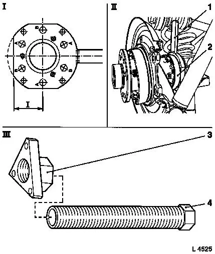
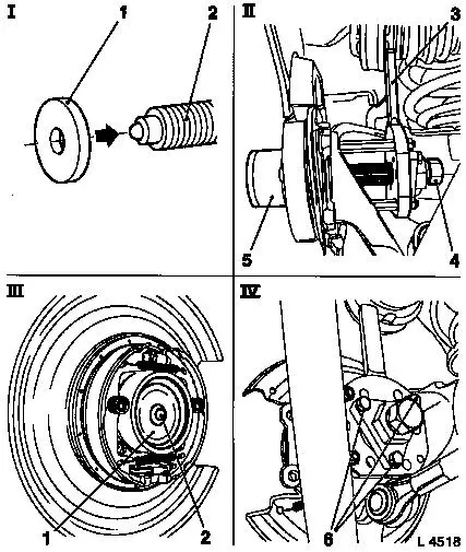
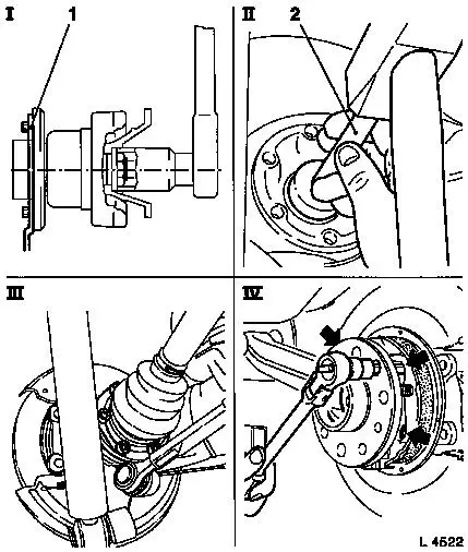
Remove rust and dirt from contact surfaces of brake disc and
wheel hub.
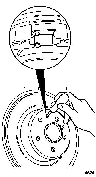
 Install
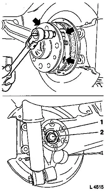
Brake disc to front wheel hub – tightening torque 4 Nm / 3
lbf. ft.
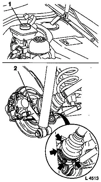
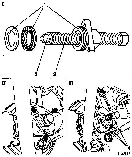
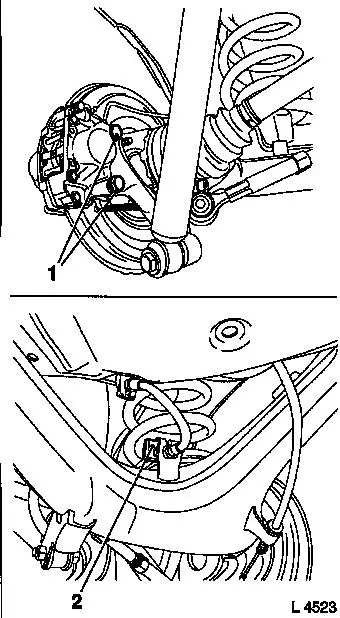
Place brake calliper with brake line on brake disc and attach to
semi-trailing arm with fastening bolts (1) – re-cut thread
and insert fastening bolts with locking compound – tightening
torque 80 Nm / 59 lbf. ft.
Attach shock absorber to semi-trailing arm – tightening
torque 110 Nm / 81 lbf. ft.
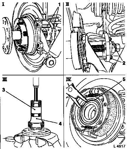
Attach brake line to brake pressure hose – tightening
torque 16 Nm / 12 lbf. ft.
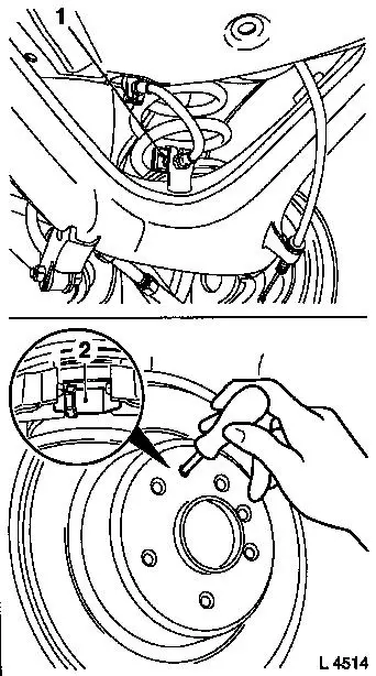
Secure brake pressure hose to bracket with retaining plate
(2).
|