|
Valve Stem Seals, Replace (Cylinder Heads
Installed)
 Remove Remove
| 1. |
Remove camshafts
| • |
see operation "Camshafts, Remove and Install"
|
|
| 2. |
Remove and install spark plugs
| • |
see operation "Spark Plugs, Remove and Install (X 25 XE, X 30
XE)" or "Spark Plugs, Remove and Install (Y 26 SE, Y 32 SE)".
|
|
| 3. |
Remove hydraulic valve lifters, intake side
|
| 4. |
Remove hydraulic valve lifters, exhaust side
|
| 5. |
Complete MKM-6086
| • |
Adjust supports MKM-6086-6
Note: Adjust support
heads (2) so that they are centred in respect of the support feet
(5) and tighten
|
| • |
Complete lever arm MKM-6086-7 (3)
| – |
With joint MKM-6086-8 and MKM-6086-10 (1)
|
|
|
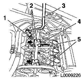
| 6. |
attach MKM-6086
| • |
Place both supports with assembly shaft (4) on cylinder to be
processed
|
| • |
Align so that is centred on cylinder head and tighten
firmly
|
|
|
|
| 7. |
Remove intake valve springs
| • |
Carefully press valve spring down
| – |
With lever arm MKM-6086-7
Note: Dismantling head
must be positioned vertically over the valve stem
|
|
Important: Note allocation
|
| • |
Remove valve keepers, plate, spring
Note: Do not use any
magnetic tools
|
|
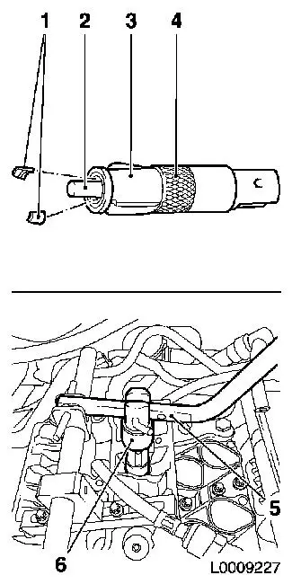
| 8. |
Install compressed air adapter MKM-6086-15 (1)
| • |
Screw into the spark plug thread of the cylinder to be
processed
|
| • |
Apply compressed air to cylinder
|
|
|
|
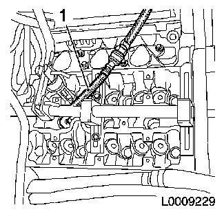
| 9. |
Renew valve shaft seals (1)
| • |
Place new valve stem seal on valve stem
Note: Coat new valve
stem seals with oil
|
| • |
Drive in with KM-835-A to the
stop
|
|
|
|
| 10. |
Complete assembly head MKM-6086-100-1
(3)
| • |
Insert thrust piece MKM-6086-100-12
(2)
Note: Follow
manufacturer's instructions
|
|
| 11. |
Install intake valve springs
Important: Insert valve keepers
(1) with the taper towards the valve
|
| • |
Insert valve springs, valve cups
|
| • |
Insert valve keepers in assembly head MKM-6086-100-1
| – |
Push tensioning sleeve (4) in the direction of the lever arm
mounting
|
| – |
Slide clamping sleeve towards valve
|
|
| • |
Attach mounting head to lever arm
|
| • |
Carefully press valve spring down
Important: Assembly head must be
positioned vertically above the valve stem. Valve keepers must
engage audibly.
|
| – |
With lever arm MKM-889-12
|
|
|
|
|
Important: Do not make a 2nd
attempt without checking that both valve keepers are seated in the
assembly head.
|
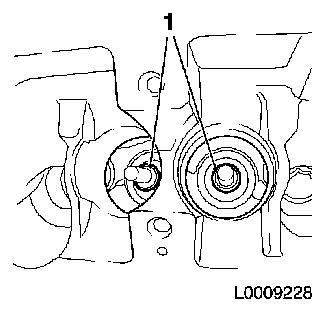
| 12. |
Check installation position
| • |
Inspect seat of valve keepers visually
|
|
| 13. |
Change over MKM-6086
| • |
From intake to exhaust side
|
|
| 14. |
Remove exhaust side valve springs
| • |
Carefully press valve spring down
| – |
With lever arm MKM-889-12
Note: Dismantling head
must be positioned vertically over the valve stem
|
|
Important: Note allocation
|
| • |
Remove valve keepers, valve cups, springs
Note: Do not use any
magnetic tools
|
|
 Install
| 15. |
Renew valve shaft seals
| • |
Place new valve stem seal on valve stem
Note: Coat new valve
stem seal with oil
|
| • |
Drive in with KM-835-A to the
stop
|
|
| 16. |
Install valve springs on exhaust side
| • |
Insert valve springs, plate
|
| • |
Insert valve keepers in assembly head MKM-6086-100-1
Important: Insert valve keepers
with the taper towards the valve
|
| – |
Push tensioning sleeve in the direction of the lever arm
mounting
|
| – |
Slide clamping sleeve towards valve
|
|
| • |
Attach mounting head to lever arm
|
| • |
Carefully press valve spring down
Important: Assembly head must be
positioned vertically above the valve stem. Valve keepers must
engage audibly.
|
| – |
With lever arm MKM-6086-7
|
|
|
| 17. |
Remove compressed air adapter MKM-6086-15
|
| 19. |
Insert hydraulic valve lifters, exhaust side
Note: Coat sliding
surfaces with engine oil
|
| 20. |
Insert hydraulic valve lifters, intake side
Note: Coat sliding
surfaces with engine oil
|
| 21. |
Replace more valve stem seals
Note: Proceed by
analogy with the other cylinders, whereby the support feet of MKM-6086 must be positioned appropriately in
each case
|
| 22. |
Install spark plugs
| • |
see operation "Spark Plugs, Remove and Install (X 25 XE, X 30
XE)" or "Spark Plugs, Remove and Install (Y 26 SE, Y 32 SE)".
|
|
| 23. |
Install camshafts
| • |
see operation "Camshafts, Remove and Install"
|
|
|
