vauxhall Workshop Repair Guides

Vauxhall Workshop Service and Repair Manuals

Diagnostic Information and Procedures > < F0: DATA LIST - Test Step 20 ENGINE SPEED LIM

Knock Sensor, Remove and Install (X 20 XEV)

  Remove

Disconnect ground cable from battery.

Disconnect crankcase ventilation hose (1) from cylinder head cover and from air intake hose. Disconnect crankcase ventilation hose (2) from cylinder head cover.

Detach wiring harness plug (3) from idle speed stepper motor and ground cable (4) from fastening pin.

Object Number: 2392949  Size: DEFAULT

Note:   There are a total of 6 plug connections on the underside of the plug strip. Illus. E 5392 shows the injector plug connections (positions 1 to 4).

  Remove

Press retaining clip for injectors for 1st cylinder and 4th cylinder in plug strip towards engine side (with screwdriver) – collect retaining clips with bar magnet.

Object Number: 2387853  Size: DEFAULT

Raise plug strip.

Disconnect wiring harness plug (1) for knock sensor from plug strip.

Note cable routing for knock sensor.

Remove starter – see operation "Starter, Remove and Install". If necessary – remove intake manifold support from intake manifold and cylinder block.

Object Number: 2392265  Size: DEFAULT

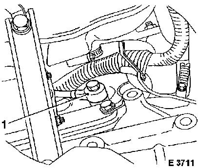
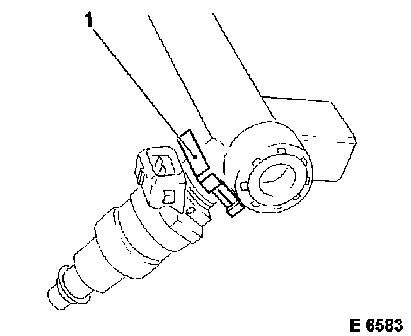
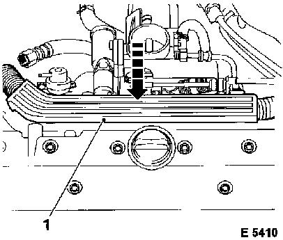
Remove knock sensor (1) from cylinder block.

Caution

The entire contact surface of the knock sensor must lie directly on the cylinder block – ensure utmost cleanliness. Do not use washers, spring washers or toothed washers. Observe tightening torque exactly.

  Install

Attach knock sensor to cylinder block – tightening torque 20 Nm / 15 lbf. ft.

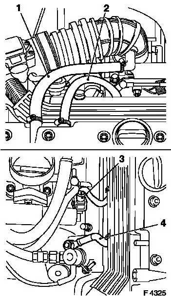
If necessary – attach intake manifold support to cylinder block and intake manifold – tightening torque 25 Nm / 18 lbf. ft.

Install starter – see operation "Starter, Remove and Install".

Object Number: 2386972  Size: DEFAULT

Note knock sensor cable routing – cable runs between 3rd and 4th cylinders of intake manifold. Fasten knock sensor wiring harness plug to plug strip.

Caution

If the spring clips (1) for the injectors are incorrectly positioned, this will prevent the plug strip from engaging. Align all spring clips properly so that correct plug strip contact with the injectors is guaranteed.

Object Number: 2388575  Size: DEFAULT

  Install

Attach plug strip (1) to injectors. Ensure correct seating, plug strip must engage audibly.

Attach ground cable to fastening pin and wiring harness plug to idle speed stepper motor. Attach crankcase ventilation hoses to cylinder head cover and to air intake hose. Connect ground cable to battery.

Object Number: 2387870  Size: DEFAULT


Related Literature Units
-
-
-

Diagnostic Information and Procedures > < F0: DATA LIST - Test Step 20 ENGINE SPEED LIM