|
Electronic Printed Circuit Board for Speedometer
and Fuel Gauge, Replace (up to Model Year '97)
|
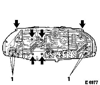
Caution
Do not remove Torx screws designated 1. Risk of destruction.
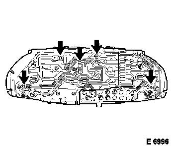
 Remove Remove
Remove instrument assembly – see operation "Instrument
Assembly, Remove and Install". 6 screws (arrows) from rear.
|
|
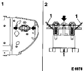
Remove
|
Lever off carefully central connection of temperature gauge and
fuel gauge using 2 screwdrivers, size 2-3 (section 2 pos. 1), until
central contact pin (arrow) is released.
|
|
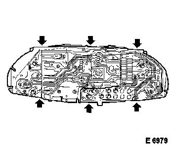
Remove
|
Release 6 clips (arrows) and remove instrument housing from
cover. Install protection cover on tachometer/speedometer unit.
Caution
Never move speedometer needle.
|
|
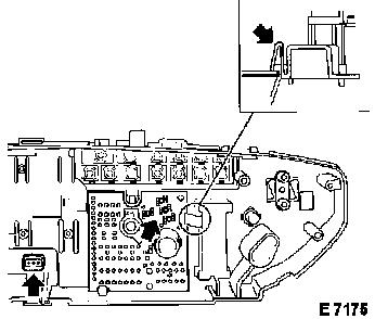
Remove
|
Remove 4 screws from front side, remove instruments carefully
from instrument housing.
Release clip, if present. Remove printed circuit board from
instrument housing.
|
|
 Install
|
Printed circuit board in instrument housing. Instruments in
instrument housing, 4 screws in front side, protection cover from
speedometer. Cover on instrument housing and fasten with 6
screws.
Caution
Check all connections (arrows) from printed circuit board to
instrument for correct seat.
Install
Install instrument assembly.
|
|
|
