Intake Manifold, Remove and Install (X 18 XE1)
 Remove, Disconnect Remove, Disconnect Remove engine cover from cylinder head cover. Detach wiring harness plug (2) and vacuum hoses (1) from tank vent valve and remove tank vent valve from air cleaner housing - when detaching the vacuum hoses from the valve body, ensure that the valve connections are not damaged. Damaged valves must be replaced.
 Important! Important! Damaged valve connections may lead to vehicle fires as a result of leaks. | 
|
Remove, Disconnect Remove upper part of air cleaner housing with air duct pipe - see illustrations "Air Cleaner Housing, Air Duct". Remove ribbed V-belts - see operation "Ribbed V-belts, Remove and Install". Detach fastening bolt for intake manifold support (1) at intake manifold and only release at cylinder block - swing support to one side. | 
|
Remove, Disconnect Detach or disconnect wiring harness plug from crankshaft pulse pick-up (1) and switchover valve solenoid valve (2). Detach accelerator Bowden cable (4) and lay aside to the rear. For version with cruise control: Detach cruise control Bowden cable (3). Remove engine vent hoses (5) from cylinder head cover. Disconnect wiring harness plug for camshaft sensor (6). Place cable bundle to one side. Detach ground cable (7) from alternator bracket. | 
|
Remove, Disconnect Disconnect wiring harness plug (1) from throttle valve adjuster and from knock sensor (2). Disconnect wiring harness plug (3) from ignition module and from exhaust gas recirculation valve (4). Detach wiring harness plug for dynamic oil level control sensor (5), for coolant temperature sensor (6) and for coolant temperature sender (7). | 
|
Remove, Disconnect Release both wiring harness plugs (1) in direction of arrow and detach from engine control unit. Remove ground cable (3) from engine control unit. Remove wiring harness plug for knock sensor (4) from bracket. Remove fastening bolts (2) and remove engine control unit. | 
|
Remove, Disconnect Detach vacuum hose for tank vent valve (1) from throttle body. Remove coolant hoses (2) from throttle body - collect escaping coolant. Detach coolant line (6) from intake manifold and cylinder head cover and place to one side. Detach coolant hose (heater) (4) from intake manifold. Connect Fuel Pressure Gauge KM-J-34730-91 to test connection on fuel distributor pipe. Reduce fuel pressure by opening valve on fuel pressure gauge. Collect escaping fuel in suitable container - observe safety regulations and national legislation. Detach fuel feed line (3) from fuel distributor pipe. Disconnect brake servo vacuum line (5) from quick fitting on intake manifold. | 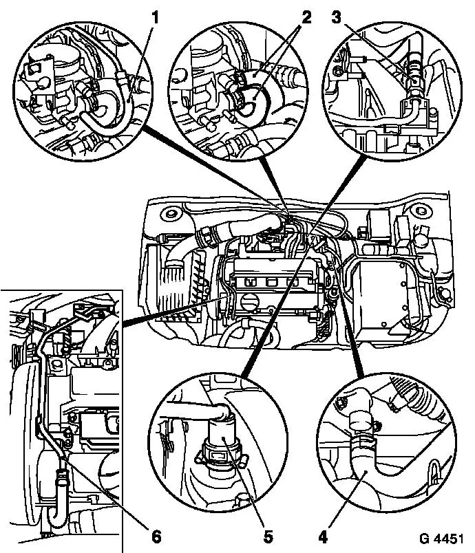
|
Remove, Disconnect Unscrew fastening bolts (arrows) (1 - enlargement at top) and remove alternator shackle. Release plug strip with wiring trough (2) (arrow), carefully detach from injectors and place to one side. Detach rear engine transport shackle (3) (enlargement below) from cylinder head. Unscrew fastening nuts (arrows) from inlet manifold and take inlet manifold (4) out of cylinder head. | 
|
 Install, Connect Install, Connect Transfer attaching parts when replacing intake manifold. Attach intake manifold to cylinder head with new gasket and new fastening nuts - tightening torque 20 Nm / 15 lbf. ft. Attach rear engine transport shackle to cylinder head - 25 Nm / 18.5 lbf. ft. Carefully attach plug strip with wiring trough to injectors - plug strip must audibly engage. Attach alternator shackle at top - tightening torque 20 Nm / 15 lbf. ft. Connect brake servo vacuum line to quick fitting on intake manifold. Attach fuel line to fuel distributor pipe - tightening torque 15 Nm / 11 lbf. ft. Attach coolant hoses to throttle body and intake manifold. Attach coolant line to intake manifold and cylinder head cover - tightening torque 8 Nm / 6 lbf. ft. Attach vacuum hose for tank vent valve to throttle body. Attach engine control unit and bolt on ground cable. Clip in wiring harness plug for knock sensor. Connect both wiring harness plugs to engine control unit and lock - ensure correct seating of wiring harness plugs.
Install, Connect Connect wiring harness plug for dynamic oil level control sensor. Connect wiring harness plug for coolant temperature sensor and coolant temperature sender. Connect wiring harness plug for ignition module and wiring harness plug for exhaust gas recirculation valve. Connect wiring harness plug for throttle valve adjuster and wiring harness plug for knock sensor. Attach ground cable to upper alternator bracket. Clip wiring harness plug for camshaft sensor into bracket and connect. Attach engine vent hoses to cylinder head cover. Install accelerator Bowden cable. For version with cruise control: Attach cruise control Bowden cable. Attach or connect wiring harness plug for crankshaft pulse pick-up and wiring harness plug for solenoid valve for switchover valve. Attach intake manifold support to intake manifold - tightening torque 20 Nm / 15 lbf. ft. Fasten intake manifold support to cylinder block - tightening torque 35 Nm / 26 lbf. ft.
Install, Connect Install ribbed V-belt - see operation "Ribbed V-belt, Remove and Install". Notice: Before assembling components of the intake system (hoses, connections, etc.), they must be cleaned of any possible contamination (grease, oil, etc.). When tightening the hose clamps, be sure to observe exactly the tightening torque of 3.5 Nm / 2.6 lbf. ft.
Important! It is only ensured that the intake system is free of leaks, thus ensuring operational safety of the engine, if the hose clamps are tightened correctly to the prescribed tightening torque.
Install, Connect Install air cleaner housing and air duct pipe - see illustrations "Air Cleaner Housing, Air Flow Guide". Attach tank vent valve to air cleaner housing. Connect wiring harness plug and vacuum hoses to tank vent valve. Install engine cover on cylinder head cover. Top up cooling system - see operations "Cooling System, Top up and Bleed" and "Cooling System, Check for Leaks".
|
