Subject:
Removal, installation and replacement of power steering pump
Vehicles:
Vectra-B with X 20 DTL/X 20 DTH engine, Omega-B with X 20 DTH
engine, Sintra with X 22 DTH engine.
Condition:
The removal, installation and replacement of the power
steering pump in the above vehicles was previously only anticipated in
conjunction with the auxiliary aggregates support and was also only available
as such.
Remedy:
The Aftersales department now supplies a modified power
steering pump as an installation kit for removal, installation and replacement,
described as follows, without the auxiliary aggregates bracket.
Note:
These operations will be incorporated in the next edition of
the relevant Service literature and Labour Time Guide.
|
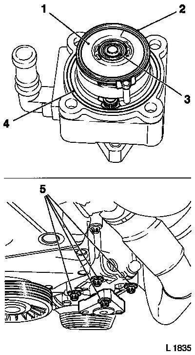
Installation Kit
1 Power steering pump
2 Seal kit
3 Transport cover
Individual Components
4 Auxiliary aggregates support
5 Retaining ring
6 Rear pump cover
7 Centring pins
8 Pump
9 Front pump cover
10 Seal ring for pump housing
|


|
|
Power Steering Pump, Remove and Install or Replace
(Vectra-B with X 20 DTL or X 20 DTH Engines)
Remove, Disconnect
Unclip relay/fuse holder from air cleaner housing. Remove
air cleaner housing with intake hose.
Remove lower engine compartment cover.
Place collecting basin underneath, unscrew coolant drain
bolt on radiator and drain coolant. Detach coolant hoses from thermostat
housing.
Release fastening bolts on power steering pump pulley.
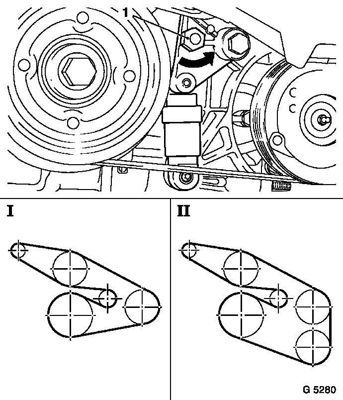
Mark running direction of ribbed V-belt. Tension ribbed
V-belt tensioner by means of hex lug (1) in direction of arrow
(anti-clockwise) and remove ribbed V-belt from power steering pump pulley.
Remove pulley from power steering pump.
Remove hydraulic lines from power steering pump.
Remove fastening bolts (2) for power steering pump from
auxiliary aggregates support and remove power steering pump.
Remove transport cover from power steering pump
installation kit.
|

|
|
Install, Attach
Replace seal rings (3 and 4) on new power steering pump
with the gaskets supplied in the installation kit.
Important:
Insert new seal rings with Vaseline. Ensure that the rear
cover (1) sits correctly in the guide pins and is fastened with the retaining
ring (2).
Install, Attach
Carefully insert power steering pump in support.
Insert fastening bolts (5), tighten by hand and then
tighten evenly alternating crosswise - tightening torque 20 Nm/15 lbf.
ft.
|

|
|
Install, Attach
Attach pressure line with new seal rings to power steering
pump - tightening torque 35 Nm/26 lbf. ft. Attach feed line to power
steering pump - tightening torque 2.5 Nm/2 lbf. ft. Attach pulley to
power steering pump - tightening torque 20 Nm/15 lbf. ft.
Tension ribbed V-belt tensioner by means of hex lug (1) in
direction of arrow (anti-clockwise) and install ribbed V-belt on power
steering pump pulley so that the ribbed V-belt sits correctly and the routing
is correct (see illustration).
I Routing of ribbed V-belt without air conditioning
II Routing of ribbed V-belt with air conditioning
|
|
|
Install, Attach
Attach coolant hoses (1 and 2) to thermostat housing.
Install air cleaner housing with air intake hose.
Clip relay holder/fuse carrier to air cleaner housing.
Top up coolant to "COLD" mark on coolant
compensation tank.
Important:
Only use radiator anti-freeze 90 297 545 / 19 40 656
and ensure a concentration of 50%.
Install, Attach
Top up Special Fluid DexronÒ
II to "MAX" mark in power steering fluid reservoir.
Allow engine to run warm. Turn steering wheel 2 to 3 times
approx. 45° slowly to left and to right and then twice from stop to stop.
When doing so, check fluid level in power steering fluid reservoir several
times and correct if necessary.
Switch off engine. Attach lower engine compartment cover.
Check coolant level in coolant compensation tank and
correct if necessary.
|

|
|
Power Steering Pump, Remove and Install or Replace
(Omega-B with X 20 DTH Engine)
Remove, Disconnect
Remove lower engine compartment cover.
Place collecting basin underneath, unscrew coolant drain
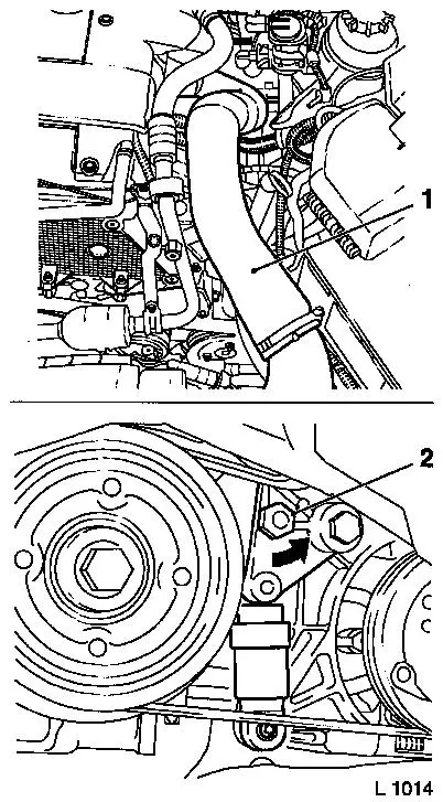
bolt on radiator and drain coolant. Remove air intake hose (1).
Detach coolant hoses from thermostat housing.
Release fastening bolts on power steering pump pulley.
Mark running direction of ribbed V-belt. Tension ribbed
V-belt tensioner by means of hex lug (2) in direction of arrow
(anti-clockwise) and remove ribbed V-belt from power steering pump pulley.
Remove pulley from power steering pump.
Remove hydraulic lines from power steering pump.
Remove fastening bolts for power steering pump from
auxiliary aggregates support and remove power steering pump.
Remove transport cover from new power steering pump.
|
|
|
Install, Attach
Replace seal rings (3 and 4) on new power steering pump
with the gaskets supplied in the installation kit.
Important:
Insert new seal rings with Vaseline. Ensure that the rear
cover (1) sits correctly in the guide pins and is fastened with the retaining
ring (2).
Install, Attach
Carefully insert power steering pump in support.
Insert fastening bolts (5), tighten by hand and then
tighten evenly alternating crosswise - tightening torque 20 Nm/15 lbf.
ft.
|
|
|
Install, Attach
Attach pressure line with new seal rings to power steering
pump - tightening torque 35 Nm/26 lbf. ft. Attach feed line to power
steering pump - tightening torque 2.5 Nm/2 lbf. ft. Attach pulley to
power steering pump - tightening torque 20 Nm/15 lbf. ft.
Tension ribbed V-belt tensioner by means of hex lug (1) in
direction of arrow (anti-clockwise) and install ribbed V-belt on power
steering pump pulley so that the ribbed V-belt sits correctly and the routing
is correct (see illustration).
I Routing of ribbed V-belt without air conditioning
II Routing of ribbed V-belt with air conditioning
|
|
|
Install, Attach
Attach coolant hoses (1 and 2) to thermostat housing.
Top up coolant to "COLD" mark on coolant
compensation tank.
Important:
Only use radiator anti-freeze 90 297 545 / 19 40 656
and ensure a concentration of 50%.
Install, Attach
Top up Special Fluid DexronÒ III to "MAX" mark in power steering fluid
reservoir.
Allow engine to run warm. Turn steering wheel 2 to 3 times
approx. 45° slowly to left and to right, then twice from stop to stop. When
doing so, check fluid level in power steering fluid reservoir several times
and correct if necessary.
Switch off engine. Attach lower engine compartment cover.
Check coolant level in coolant compensation tank and
correct if necessary.
|

|
|
Power Steering Pump, Remove and Install or Replace
(Sintra with X 22 DTH Engine)
Remove, Disconnect
Remove wiper motor cover.
Remove power steering fluid reservoir bracket (5) from air
deflector panel. Remove power steering fluid reservoir (3) from dome strut
and lay to one side.
Remove fastening bolts for dome strut (1 and 4) on spring
strut dome, detach air deflector panel and remove dome strut.
Remove fastening bolt (arrow) and raise central electrics
(2) and lay to one side. Unscrew ground cable and positive cable from
battery. Remove battery bracket and battery. Remove battery support.
|

|
|
Remove, Disconnect
Release fastening bolts on power steering pump pulley.
Mark running direction of ribbed V-belt. Tension ribbed
V-belt tensioner by means of hex lug (1) in direction of arrow
(anti-clockwise) and remove ribbed V-belt from power steering pump pulley.
Remove pulley from power steering pump.
Place collecting basin underneath. Detach hydraulic lines
from power steering pump and collect hydraulic fluid.
Remove fastening bolts (2 and arrow) for power steering
pump from auxiliary aggregates support and remove power steering pump.
Remove transport cover from new power steering pump.
|

|
|
Install, Attach
Replace seal rings (3 and 4) on new power steering pump
with the gaskets supplied in the installation kit.
Important:
Insert new seal rings with Vaseline. Ensure that the rear
cover (1) sits correctly in the guide pins and is fastened with the retaining
ring (2).
Install, Attach
Carefully insert power steering pump in support.
Insert fastening bolts (5), tighten by hand and then
tighten evenly alternating crosswise - tightening torque 20 Nm/15 lbf.
ft.
|

|
|
Install, Attach
Attach pressure line with new seal rings to power steering
pump - tightening torque 35 Nm/26 lbf. ft. Attach feed line to power
steering pump - tightening torque 2.5 Nm/2 lbf. ft. Attach pulley to
power steering pump - tightening torque 20 Nm/15 lbf. ft.
Tension ribbed V-belt tensioner by means of hex lug (1) in
direction of arrow (anti-clockwise) and install ribbed V-belt on power
steering pump pulley - ensure that the ribbed V-belt sits correctly and
the routing is correct (see illustration).
I Routing of ribbed V-belt without air conditioning
II Routing of ribbed V-belt with air conditioning
|
|
|
Install, Attach
Install battery support (1). Insert battery and install
battery bracket. Screw ground cable and positive cable to battery. Attach
central electrics to air deflector plate with fastening bolt.
Insert dome strut and attach dome strut fastening bolts to
spring strut dome and air deflector plate. Attach power steering fluid
reservoir bracket to air deflector plate. Connect power steering fluid
reservoir to bracket.
Install wiper motor cover. Top up special fluid in power
steering fluid reservoir to "C" mark.
Allow engine to run warm. Turn steering wheel several times
from stop to stop. When doing so, check fluid level in fluid reservoir
several times and correct if necessary. Switch off engine.
Important:
Power steering pump must not be allowed to run dry.
|

|
|
|
|
Parts:
|
Designation
|
Part Number
|
Catalogue Number
|
|
Power steering pump installation kit (Vectra-B)
|
09 156 916
|
09 48 379
|
|
Power steering pump installation kit (Omega-B)
|
09 156 917
|
09 48 380
|
|
Power steering pump installation kit (Sintra)
|
09 228 406
|
09 48 381
|
|
Pressure line gasket
(x 2)
|
09 156 053
|
09 48 259
|
|
Special Fluid Dexron II
1 litre
55 litres
|
90 350 342
90 350 343
|
19 40 700
19 40 701
|
|
Special Fluid Dexron III
1 litre
|
90 510 269
|
19 40 763
|
|
Special fluid (steering gear, Sintra) 1 litre
|
90 513 486
|
19 40 707
|
Time Allowances:
Op. no. Operation Description hrs Code Carline
M 0475 00 Power Steering Pump - Replace
TC: 15, 40, 42, 56, 61 1.5 X
20 DTL, X 20 DTH Vectra-B
1.2 X
20 DTH Omega-B
1.1 X
22 DTH Sintra
Additional time allowances remain unchanged.
The specified time allowances do not include the time
allowance for the vehicle set-up of .2 hrs.
For reimbursement of the vehicle set-up time of .2 hrs in
warranty claims, enter the authorisation code "T" and increase the
main operation time allowance by .2 hrs.
The authorisation code may only be used once per work
order. It may only be used more than once if the workplace and workteam are
changed at the same time.
