
Corrado L4-1781cc 1.8L SOHC SC (1991)
Ignition Hall Effect Sensor: Testing and Inspection
Checking
Federal, Canada
Hall sender unit, checking
Requirement
-
Electrical check of Digifant system OK
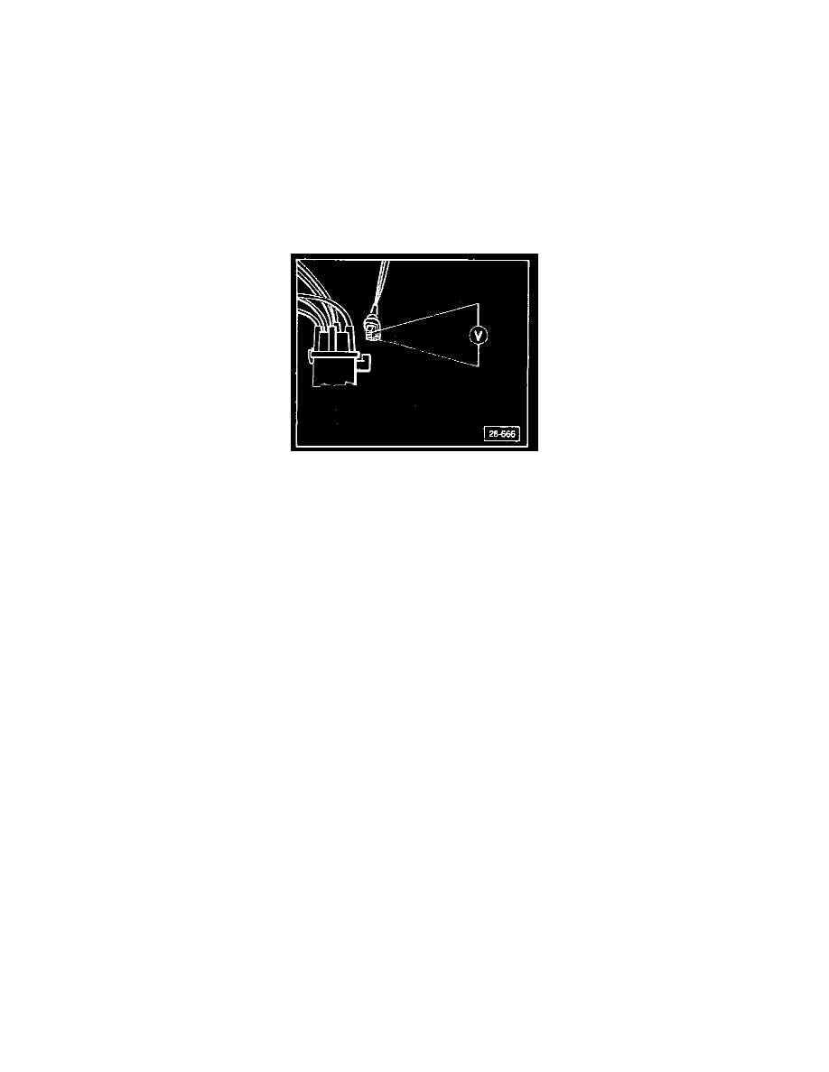
Voltage supply, checking
remove harness connector from Hall sender (on distributor)
- switch multimeter US 1119 to 20 volt range
- connect multimeter to outer terminals of harness connector
- switch ON ignition
-
10 volts minimum
If less than 10 volts
- replace Digifant control unit
If zero volts
- locate and eliminate open circuit in wiring using wiring diagram
California
Hall sender (G 40), checking
NOTE: The Hall sender can also be checked using the VAG 1598 Test box.
- perform following checks using Fluke 83 multimeter (US 1119)
-
specified values are valid when measured at a temperature between 0 and 40°C (32 and 104°F)
If measured values deviate from specified values
- check for open or short circuits using proper wiring diagram before replacing components
- use the VW 1594 adaptor kit to make connections between the multimeter and the harness connectors
CAUTION: Switch the multimeter to the appropriate measuring range before making test connections.
Voltage supply, checking
- switch OFF ignition
- disconnect harness connector from (N 41) Hall control unit
- switch multimeter to 20 Volt range