
Eurovan L5-2459cc 2.5L SOHC (1992)
6
-
Warning lights, right
-
Installation position, see Fig. 3
-
Checking LED
-
Installing, see Fig. 4
7
-
Analog clock
-
Removing and installing, see Fig. 1
8
-
Analog clock printed circuit
8A -
Digital clock printed circuit
-
Only replace printed circuit together with housing
-
Components on printed circuit Figs. = 9 & 10
9
-
Voltage stabilizer with heat sink
-
Checking, see Fig. 6
-
Removing and installing, see Fig. 7
10
-
Housing
-
Only replace housing together with printed circuit
11
-
Speed Sensor (VSS) -G54- contact plate
12
-
Bulb for digital clock
-
Black holder
-
12 V / 1.2 W
-
Installation position, see Fig. 11
-
Removing and installing, see Fig. 12.
13
-
Warning lights, left
-
Installation position, see Fig. 2
-
Installing, see Fig. 4
14
-
Turn signal warning light, left
-
Installing, see Fig. 5
15
-
Instrument cluster lighting conductor
-
Connection to printed circuit, see Fig. 10
16
-
Instrument cluster light bulb
-
Blue holder
-
12 V / 1.2 W
17
-
Speed Sensor (VSS) -G54-
-
Only with mechanical speedometer
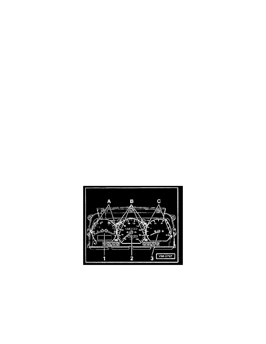
Fig. 1 Instruments, removing and installing
CAUTION!
Before beginning repairs on the electrical system:
-
Obtain the anti-theft radio security code.
-
Switch the ignition off.
-
Disconnect the battery Ground (GND) strap.
-
After reconnecting battery, re-code and check operation of anti-theft radio.
1
-
Fuel gauge and coolant temperature gauge additionally with digital clock or multi function indicator (MFI)
2
-
Mechanical speedometer or electronic speedometer -G21-
3
-
Analog clock or tachometer additionally with selector lever position display
-
Pull instruments -1 and 3- forward out of housing, and also electronic speedometer (instrument -2-) if equipped.
-
For mechanical speedometers -2-, remove securing screws -B- and pull instrument out forward.