
Golf Mk2
| Removing and installing wheel bearing, suspension strut and drive shaft |
 Note
Note| t | If a vehicle has to be moved after removing the drive shaft, first install an outer joint instead of a drive shaft, otherwise the wheel bearing will be damaged. |
| t | It is not permitted to weld or straighten suspension parts which bear loads or locate the front wheels |
| t | Renew self-locking nuts. |
| t | Renew corroded nuts and bolts. |
| t | Wheel bolt tightening torque: 110 Nm |

| 1 - | Self-locking nut, 60 Nm |
| q | Unbolting and bolting → Fig.. |
| 2 - | Coil spring strut |
| q | Removing → Fig. and → Fig.. |
| q | Repairing → Chapter. |
| q | Coil spring allocation → Chapter. |
| 3 - | Self-locking nut |
| q | 19 mm, 80 Nm. |
| q | 18 mm, 95 Nm. |
| 4 - | Hexagon bolt |
| q | In thinner version, also serves to correct (adjust) camber → Chapter. |
| q | Mark installation position before loosening |
| 5 - | Multi-point socket head bolt, 45 Nm |
| 6 - | Drive shaft |
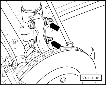
| q | To remove and install left shaft, separate wheel bearing housing/suspension strut connection → Fig.. |
| q | Repairing → Chapter. |
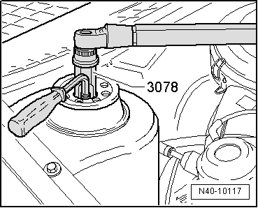
| 7 - | Self-locking hexagon nut, 265 Nm |
| q | Only loosen and tighten with the vehicle standing on its wheels (danger of accident). |
| 8 - | Washer |
| 9 - | Self-locking hexagon nut, 35 Nm |
| 10 - | Track rod |
| q | Pressing off steering arm → Fig.. |
| 11 - | Hexagon bolt, 25 Nm |
| 12 - | Brake caliper |
| q | Do not disconnect brake hose when working on front suspension |
| q | Tie in position with wire or similar |
| 13 - | Brake pads |
| q | Removing and installing → Chapter |
| 14 - | Self-locking hexagon nut, 50 Nm |
| 15 - | Brake disc |
| q | Allocation → Chapter and → Chapter. |
| 16 - | Cross-head screw |
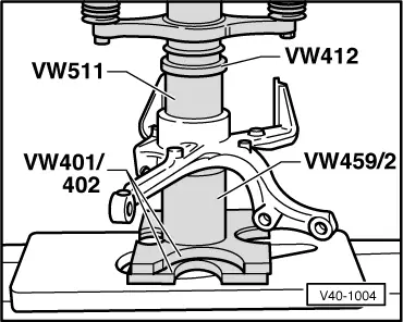
| 17 - | Wheel hub |
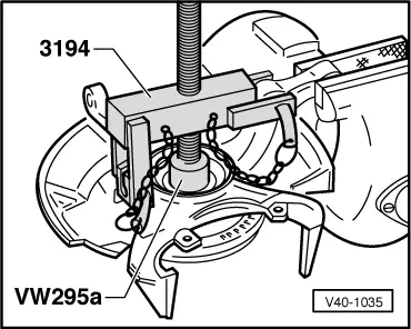
| q | Pressing out → Fig. |
| q | Pressing in → Fig.. |
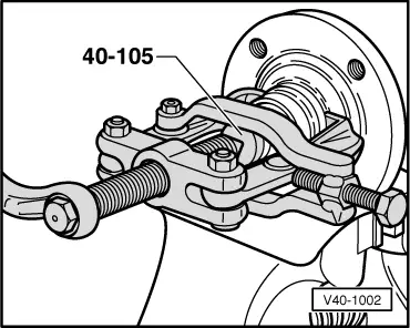
| q | Pulling off inner race → Fig. |
| q | Modification: As of 08.87, bearing seat Ø 40 mm; up to 07.87, bearing seat Ø 35 mm. |
| 18 - | Wheel hub |
| q | Only on vehicles with ABS. |
| q | Pressing out → Fig. |
| q | Pressing in → Fig.. |
| q | Pulling off inner race → Fig. |
| 19 - | Speed sensor rotor |
| q | Only on vehicles with ABS. |
| 20 - | Hexagon bolt, 10 Nm |
| 21 - | Cover plate |
| q | Adapted to modified bearing seat. |
| 22 - | Retaining ring |
| q | Ensure proper seating. |
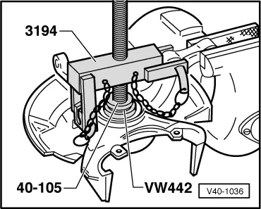
| 23 - | Wheel bearing |
| q | Pressing out → Fig. |
| q | Renew; is destroyed when pressed out |
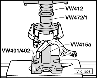
| q | Pressing in → Fig.. |
| q | Modification: As of 08.87, wheel bearing Ø inner 40 mm, outer 72 mm; up to 07.87, wheel bearing Ø inner 35 mm, outer 66 mm. |
| 24 - | Wheel bearing housing |
| q | Modification: As of 08.87, bearing seat Ø 72 mm; up to 07.87, bearing seat Ø 66 mm; suspension strut arm 5.5 mm longer towards centre of vehicle. |
| q | Before removing, mark installation position on suspension strut clamp. |
Note
|
|
|
|
|
|
|
|
|
|
|
|