
Golf Mk4
|
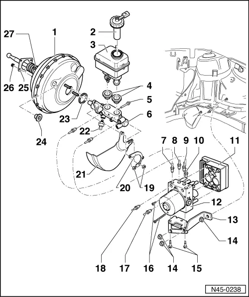
| 1 - | Brake servo |
| q | On petrol engines the vacuum required is taken from the intake manifold |
| q | On diesel engines an vacuum pump is installed to create the required vacuum |
| q | Some vehicles additionally have an electrical vacuum pump -V192- |
| q | Functional check → Chapter |
| q | Removing and installing → Chapter |
| q | Allocation → Electronic Parts Catalogue (ETKA) |
| q | Functional check: |
| – | With engine switched off, depress brake pedal firmly several times (to exhaust the vacuum in the unit) |
| – | Now depress brake pedal with average foot pressure, hold and start engine If the servo unit is working properly, the pedal will give slightly under foot (servo assistance becomes activated) |
| q | If faulty renew complete (check all vacuum lines first) |
| q | Non-return valve (in vacuum hose) → Anchor |
| q | Separating from brake pedal → Chapter |
| q | Removing and installing → Chapter |
| 2 - | Cap |
| 3 - | Brake fluid reservoir |
| 4 - | Sealing plug |
| q | Coating with brake fluid and pressing into brake master cylinder |
| 5 - | Retaining pin |
| q | Insert through brake master cylinder |
| 6 - | Brake master cylinder |
| q | On vehicles with ABS/EDL/TCS/ESP, the pressure sensor -G201- is additionally installed → Chapter |
| q | Cannot be repaired. If faulty, renew complete |
| 7 - | Brake line connection |
| q | Brake master cylinder/primary piston circuit to hydraulic unit |
| 8 - | Brake line connection |
| q | Hydraulic unit to front left brake caliper |
| 9 - | Brake line connection |
| q | Hydraulic unit to front right brake caliper |
| 10 - | Brake line connection |
| q | Brake master cylinder/secondary piston circuit to hydraulic unit |
| 11 - | Control unit |
| q | Do not disconnect connector before self-diagnosis |
| q | Removing and installing → Chapter |
| 12 - | ABS hydraulic unit |
| q | The hydraulic pump -V64- and the inlet/outlet valves in the hydraulic unit are checked by self-diagnosis |
| q | The hydraulic pump -V64- and valve block must not be separated from one another |
| q | Removing and installing → Chapter |
| q | When changing the hydraulic unit, always seal the old part with the plugs from the repair set Part No. 1H0 698 311 A |
| 13 - | Bracket |
| 14 - | Cap nut, 20 Nm |
| 15 - | Bolt, 8 Nm |
| 16 - | Bolt, Torx socket head E5, 4 Nm |
| 17 - | Brake line connection |
| q | Hydraulic unit to rear left wheel cylinder/brake caliper |
| 18 - | Brake line connection |
| q | Hydraulic unit to rear right wheel cylinder/brake caliper |
| 19 - | Self-locking hexagon nut, 20 Nm |
| 20 - | Retaining plate |
| q | Used to secure the wiring harness |
| 21 - | Heat shield |
| q | Allocation → Electronic Parts Catalogue (ETKA) |
| 22 - | Brake pressure sender 1 -G201- |
| q | Only installed on vehicles with ABS/EDL/TCS/ESP → Chapter |
| 23 - | Seal |
| q | Renew |
| 24 - | Sealing plug |
| q | Connection for vacuum hose |
| 25 - | Seal |
| q | For brake servo |
| 26 - | Self-locking hexagon nut, 20 Nm |
| 27 - | Boot |
| q | Ensure it is seated correctly, danger of suction noises |