volkswagen Workshop Repair Guides

Volkswagen Workshop Service and Repair Manuals

Accelerator mechanism > < Checking accelerator pedal position sender
Checking voltage supply and wiring to control unit
–  Remove stowage compartment on driver's side: → Rep. Gr.68.
–  Pull 6-pin connector off accelerator pedal position sender.
–  Switch on ignition.
–  Connect multimeter to measure voltage at the following connector contacts:
Contact 1 + earth
Contact 1 + 5
Contact 2 + earth
Contact 2 + 3
   
Specification: min. 4.5 V
–  Switch off ignition.
If the specifications are not obtained:
  N20-10151
–  Connect adapter leads, 121-pin -V.A.G 1598/31- to control unit wiring harness. The engine control unit remains disconnected.
–  Check wiring between test box and 6-pin connector for open circuit using current flow diagram:
Contact 1 and test box socket 72
Contact 2 and test box socket 73
Contact 3 and test box socket 36
Contact 4 and test box socket 35
Contact 5 and test box socket 33
Contact 6 and test box socket 34
  N24-0943
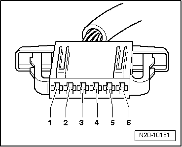
Wire resistance: max. 1.5 Ω
–  Also check wires for short to one another, short circuit to vehicle earth and to battery positive. Specification: ∞Ω
If no fault in lines is detected:
–  Renew accelerator pedal position senders → Item
Vehicles with automatic gearbox:
On vehicles with automatic gearbox, the gearbox control unit must also be adapted electronically: → Rep. Gr.01.
  N20-10151

Accelerator mechanism > < Checking accelerator pedal position sender