
Golf Mk4
 Note
Note
|
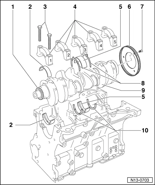
| 1 - | Sprocket |
| 2 - | Bearing shells 1, 2, 3, 4 and 5 |
| q | Classification for ordering spare parts → Fig.. |
| q | For bearing cap without oil groove. |
| q | For cylinder block with oil groove. |
| q | Do not interchange used bearing shells (mark). |
| 3 - | 65 Nm +90 ° (1/4 turn) further |
| q | Renew. |
| q | Threaded along complete length. |
| q | To measure radial clearance of crankshaft, tighten to 65 Nm. |
| 4 - | Bearing cap |
| q | Bearing cap 1: pulley end. |
| q | Bearing cap 3 with recesses for thrust washers |
| q | Bearing shell retaining lugs in cylinder block and bearing caps must be above one another. |
| 5 - | Bearing shell 3 |
| q | → Item |
| q | Do not interchange used bearing shells (mark). |
| 6 - | Sender wheel |
| q | Renew. |
| q | For engine speed sender -G28- |
| q | Can only be installed in one position. Holes are offset. |
| 7 - | 10 Nm + 1/4 turn (90°) further |
| q | Renew. |
| 8 - | Thrust washer |
| q | For bearing cap, bearing 3. |
| q | Note securing position. |
| q | Lettering points towards bearing block. |
| 9 - | Crankshaft |
| q | Axial clearance new: 0.07...0.23 mm, wear limit: 0.30 mm. |
| q | Check radial clearance with Plastigage new: 0.01...0.04 mm, wear limit: 0.07 mm. |
| q | Do not rotate crankshaft when checking radial clearance. |
| q | Crankshaft dimensions → Chapter. |
| 10 - | Thrust washer |
| q | For cylinder block, bearing 3. |
| q | Lettering points towards bearing block. |
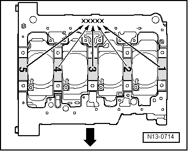
| Letter on cylinder block | Bearing colour | |
| S | = | Black |
| R | = | Red |
| G | = | Yellow |
Note
|