volkswagen Workshop Repair Guides

Volkswagen Workshop Service and Repair Manuals

Safety precautions when working on fuel supply system > < Installation position of fuel tank screw-type clip
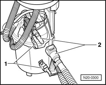
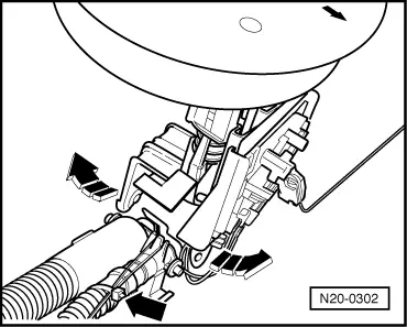
Removing, installing and checking suction jet pump: vehicles with all-wheel drive
On vehicles with all-wheel drive, fuel tank shape makes it necessary to pump fuel away from fuel gauge sender 2 -G169-, → Item, to fuel delivery unit using suction jet pump. Suction jet pump function is based on physical principle. It is driven by an additional connection from the fuel pump via the fuel supply.
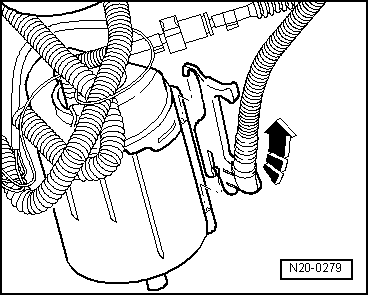
  Note
Check is only required if engine stalls due to lack of fuel, although fuel gauge sender indicates fuel tank 1/4 full.
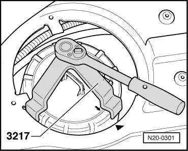
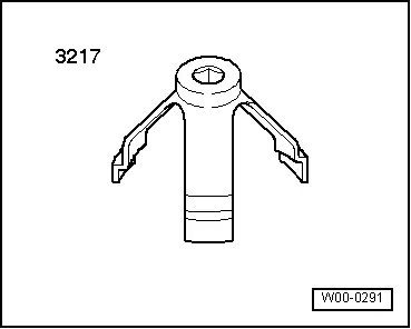
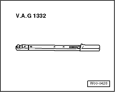
Special tools and workshop equipment required
   
t  Union nut tool -3217-
  W00-0291
t  Torque wrench -V.A.G 1332--V.A.G 1332- (40...200 Nm)
Test prerequisites
l  Fuel tank must be drained.
l  After fault finding programme, both fuel gauge senders must be checked and OK → Current flow diagrams, Electrical fault finding and Fitting locations.
Procedure
–  Note safety precautions before beginning work → Chapter.
  WARNING
Fuel system is under pressure! Before loosening hose connections, wrap a cloth around connection. Then release pressure by carefully pulling hose off connection.
–  First check whether a coded radio is fitted. If so, obtain anti-theft coding.
–  With ignition switched off, disconnect battery earth strap.
–  Unplug 4-pin connector, pull off fuel hoses from fuel delivery unit (right side of vehicle) and remove fuel delivery unit → Chapter.
  Note
Press circlip in to release fuel lines.
  W00-0428
–  Disconnect 2-pin connector -1- and supply line hose coupling -2- to suction jet pump.
  Note
Press circlip in to release fuel lines.
  N20-0300
–  Raise fuel delivery unit slightly and remove return line with bracket -arrow- upwards.
  N20-0279
–  Then screw down union unit of fuel gauge sender 2 -G169- on left side of vehicle.
–  Raise fuel gauge sender 2 -G169- upwards as far as possible.
  N20-0301
–  Disconnect cable ties on fuel line -arrow- and carefully spread open suction jet pump mounting on fuel gauge sender 2 -G169-.
–  Then unclip and remove suction jet pump with supply and return lines on fuel gauge sender 2 -G169-.
–  Check whether fuel lines are firmly mounted on suction jet pump and are not damaged.
–  Also check suction jet pump for any soiling.
If no defect can be found:
–  install suction jet pump and fuel gauge sender 2 -G169- in reverse sequence.
  Note
t  Please note that, before fitting fuel delivery unit and fuel gauge sender 2 -G169-, insert seal dry into fuel tank opening.
t  Moisten seal with fuel only when installing flange or fuel delivery unit.
t  Check fuel hoses for secure seating.
  N20-0302

Safety precautions when working on fuel supply system > < Installation position of fuel tank screw-type clip