
Golf Mk4
| Removing and installing parts of ignition system |
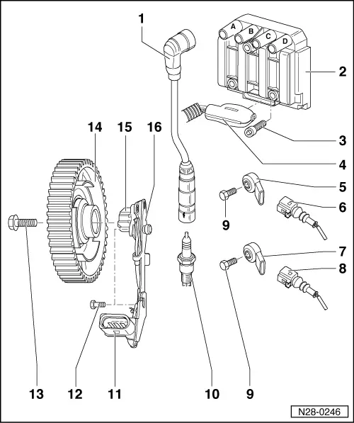
| 1 - | Ignition cable |
| q | 4…8 kΩ |
| q | With suppressor connection and spark plug connector. |
| q | Check for continuity. |
| q | Remove spark plug connector using puller -T10112-. |
| 2 - | Ignition coil 1 with output stage -N70-, ignition coil 2 with output stage -N127-, ignition coil 3 with output stage -N291- and ignition coil 4 with output stage -N292- |
| q | With identification for ignition cables: |
| A = cylinder 1 |
| B = cylinder 2 |
| C = cylinder 3 |
| D = cylinder 4 |
| 3 - | 10 Nm |
| 4 - | 6-pin connector |
| 5 - | Knock sensor 1 -G61- |
| q | Gold-plated contacts. |
| 6 - | 2-pin connector |
| q | For knock sensor 1 -G61-. |
| q | Gold-plated contacts. |
| q | Do not interchange. |
| 7 - | Knock sensor 2 -G66- |
| q | Gold-plated contacts. |
| q | Next to ignition transformer. |
| 8 - | 2-pin connector |
| q | For knock sensor 2 -G66-. |
| q | Gold-plated contacts. |
| q | Do not interchange. |
| 9 - | 20 Nm |
| q | The torque setting influences the function of the knock sensor. |
| 10 - | Spark plug, 25 Nm |
| q | Type and electrode gap → Chapter. |
| q | To remove and install, pull off connection from outer injectors. |
| q | Remove and install using spark plug socket and extension -3122 B-. |
| 11 - | Connector |
| q | Gold-plated contacts. |
| q | 3-pin. |
| 12 - | 10 Nm |
| 13 - | 100 Nm |
| q | Use counterhold tool -3415- to loosen and tighten. |
| 14 - | Camshaft pulley |
| q | With screen for Hall sender -G40-. |
| q | Remove and install → Chapter. |
| 15 - | Hall sender -G40- |
| 16 - | Bracket |
| q | For Hall sender -G40-. |